5. Frames and Network Interaction
When devices connect to Wi-Fi networks and information flows through the network, a number of different frames are used in order to ensure everything gets through as efficiently as possible. Capturing and analyzing this traffic will be critical to understanding and exploiting Wi-Fi networks.
In this module, we'll begin to understand more about frames used in Wi-Fi networks, including their headers and fields. We will also learn how wireless devices interact with various types of networks.
We recommend that students work their way through this content slowly and take their time. In particular, we recommend inspecting each capture file before moving on. Students can also return to this module for future reference.
Throughout this module we will be inspecting several files with Wireshark. For example, when we discuss beacon frames, we will inspect a Pcap file with beacon frames. Some sections of this module begin by noting an available reference file. To download the file, follow the link in the footnote.
This module presents an excellent opportunity to get even more comfortable with Wireshark while following along with the content. In some cases, we may focus our attention on a particular frame or series of frames.
5.1. Packets vs Frames
Packets and frames are not interchangeable terms. To understand more about them, it may be helpful to quickly review the Open Systems Interconnection Model (OSI), which is a conceptual model of how systems communicate over a network. A full explanation is outside the scope of this module, but a cursory explanation might be helpful.
| Layer | Description |
|---|---|
| 7. Application Layer | Human-computer interaction layer, where applications can access the network services |
| 6. Presentation Layer | Ensures that data is in a usable format and is where data encryption occurs |
| 5. Session Layer | Maintains connections and is responsible for controlling ports and sessions |
| 4. Transport Layer | Transmits data using transmission protocols including TCP and UDP |
| 3. Network Layer | Decides which physical path the data will take |
| 2. Data Link Layer | Defines the format of data on the network |
| 1. Physical Layer | Transmits raw bit stream over the physical medium |
Table 1 - The OSI model
Each layer in the OSI model is stacked and has a specific purpose. For example, the Data Link layer is where MAC headers exist. These headers help determine where the packet should go as it travels between two devices on the same network.
When we capture packets, we capture them at the Data Link layer, which includes the frame. The frame contains authentication as well as additional information about the AP. Capturing packets is generally the starting point for all other Wi-Fi attack vectors, so understanding packets, and frames in particular, is an excellent place to begin.
A packet is the protocol data unit for the network layer (3), and a frame is a unit in the data link layer (2). Packet capture is actually a misnomer because some hardware can capture at layer 3, but sometimes also at layer 2. Some specialized tools can even do layer 1.
In spite of this, "Packet Capture" has become a common term for data captured at either layer 2 or 3. In our case, all of our captures, and most of the tools we will use, operate at layer 2.
5.2. 802.11 MAC Frames
Let's begin by reviewing the base structure of a 802.11 MAC frame in Figure 1.

Figure 1: 802.11 MAC Frame
The structure is split in three parts. First, the MAC Header contains fields common for almost all frames. The first few fields are mandatory. Others may be present depending on the specific frame.
Next, the Frame body carries data or contains additional information. Not all frames will use this section.
Finally, the Frame Check Sequence (FCS) is the Cyclic Redundancy Check (CRC) of the current wireless frame. A CRC is performed over all previous fields to generate the FCS. The frame FCS is re-calculated once the frame arrives at the destination. If it is identical to the one received, then the frame is received without errors. It sometimes isn't present in the captured frames.
Warning
In capture files, sometimes Radiotap headers come before the MAC header. These headers are placed by the driver on the receiver, and contain metadata for the specific frame, including the signal level, the rate, the channel it was received on, and other information. The content and size vary from one driver to another and sometimes from one frame to another.
5.2.1. MAC Header
The following image shows the details of the Header field of a 802.11 MAC frame.
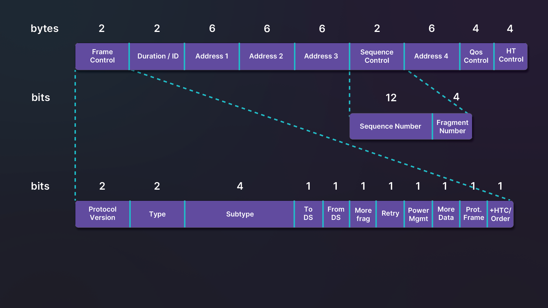
Figure 2: 802.11 MAC Header
The MAC Header contains a number of fields, and some of them are subsequently split in smaller sections. We'll explore the most import ones and briefly explain each of the fields' content.
5.2.2. Frame Control Field
- Protocol Version - This field provides the version of the 802.11 protocol used. This value is currently 0.
- Type - The type is most important field in the frame, and it determines the function of the frame, as well as the presence of some other fields in the frame. There are four different frame types with corresponding values: management (0), control (1), data (2), and extension (3). We will cover the first three later in this module. The fourth is a rare exception, so we won't cover it.
- Subtype - Each frame type can have one of several subtype field values. These determine the specific function and define the payload.
- To DS and From DS - These fields indicates whether the frame is going into a distribution system (ToDS) or exiting the distribution system (FromDS).
- More frag - This field indicates whether more fragments of the frame will follow this one.
- Retry - The retry field tells us if the frame is being retransmitted. A retransmit occurs when unicast frames aren't acknowledged in time.
- Power Mgmt - This will show us whether the sending client is in active mode (0) or power-save mode (1).
- More data - This field indicates if there is data buffered for a client.
- Protected Frame - This will reveal whether or not encryption or authentication are used in the frame.
- +HTC/Order - This field tells us if the frame contains an HT Control Field. In some rare instances, it is used to indicate that the frame is being sent using the Strictly-Ordered service class.
5.2.3. Duration/ID
Depending on the frame type and subtype, Duration/ID can have a different meaning. In Power-Save Poll frames (type 1, subtype 10), it contains the client Association Identity (AID) in the 14 least significant bits. The two most significant bits are set. When required, Duration/ID is the duration of the frame in microseconds. In some instances, it has a fixed value of 32768.
5.2.4. Addresses
The following table represents the different cases of these addresses, depending on the From/To DS bits in the Frame Control field.
| FromDS | ToDS | Address 1 | Address 2 | Address 3 | Address 4 |
|---|---|---|---|---|---|
| 0 | 0 | Destination Address | Source Address | BSSID | n/a |
| 0 | 1 | BSSID | Source Address | Destination Address | n/a |
| 1 | 0 | Destination Address | BSSID | Source Address | n/a |
| 1 | 1 | Recipient Address | Transmitter Address | Destination Address | Source Address |
Table 2 - Meaning of the 3 or 4 addresses based on ToDS and FromDS value
The first case, where ToDS and FromDS are both set to 0, will occur in IBSS mode (ad-hoc) or when the frame is a management or control frame. The FromDS and ToDS bits are not set as is the case when two clients communicate with one another directly, but this is rarely the case nowadays.
When only ToDS is set, the traffic is coming from a client and meant to reach either the AP or anything connected to it. This would be the case with a ping (ICMP request).
When only FromDS is set, the traffic is going from the AP to the client. Recalling the previous example, this would be a response to the ping.
When both are set, it indicates we are in WDS mode. In this case, one AP is talking to the another, which is why the fourth address field is present in the frame.
5.2.5. Sequence Control
The Sequence Control field consists of two sub-fields and is used to recognize frame duplication.
The Sequence Number (12 bit) subfield indicates the sequence number of each frame. The sequence number is the same for each frame sent for a fragmented frame. The value range for this field is 0-4095. When it reaches 4095, the next sequence will be 0.
The Fragment Number (4 bit) subfield indicates the number of each fragment of a frame sent. The value range for this field is 0-15.
5.2.6. QoS control and HT Control Fields
The presence of the QoS control and HT Control fields depend on other values in the frame body. The QoS Control is present only in Quality of Service (QoS) data frames to indicate the quality of service parameters. The HT Control is only present if the +HTC/Order bit is set.
5.3. Frame Types
Let's explore the structure of the common frames we'll encounter on Wi-Fi networks. As we go, we'll inspect an example for each of one. In particular, we will be focused on aspects of the frame types that help describe how devices interact with each other.
We will review management, control, and data frames. There is a fourth type of frames, extension frames, but it's not very common, so we will skip it.
5.3.1. Management Frames
Management frames are used to negotiate and control the relationship between APs and clients. The following table outlines the different types of wireless management frames.
| Subtype | Field Description |
|---|---|
| 0 | Association Request |
| 1 | Association Response |
| 2 | Re-association Request |
| 3 | Re-association Response |
| 4 | Probe Request |
| 5 | Probe Response |
| 6 | Measurement Pilot |
| 7 | Reserved |
| 8 | Beacon |
| 9 | ATIM |
| 10 | Disassociation |
| 11 | Authentication |
| 12 | Deauthentication |
| 13 | Action |
| 14 | Action No ACK |
| 15 | Reserved |
Table 3 - Management frames subtypes
We will cover the common frames encountered on wireless networks. All of these frames have the same structure as the base 802.11 MAC frame. The payload varies depending on the subtype.
5.3.2. Beacon
This section includes a reference file, beacon.pcap, in the Resources section.
Beacon frames are the most common frames as they are sent approximately 10 times per second. Beacons are broadcast by the AP to keep the network synchronized.
These frames contain useful information about the network such as the network name (unless SSID is hidden), the channel, the data rates available, type of encryption, and regulatory domain. They are typically sent at the lowest basic rate in order to reach the clients farthest away from the AP.
The structure of a beacon frame is as follows.
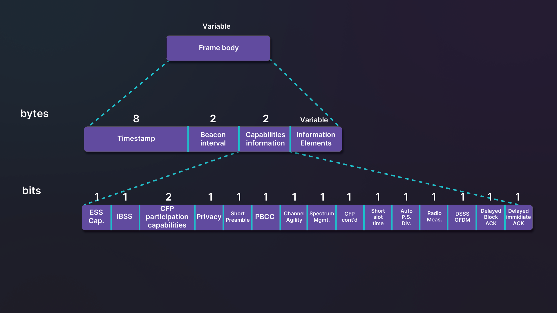
Figure 3: Beacon frame structure
Warning
Although SSID and ESSID are used interchangeably in Wi-Fi tools and AP configuration, there is a small difference. SSID is for single APs. ESSID is when multiple APs in an Extended Service Set (ESS) share the same SSID. The official name of the field in management frames is SSID.
Information in the frame's payload is split in two parts. The first part contains fixed parameters, which will always stay the same.
The first parameter includes Timestamp, which contains an 8-bytes value for a Timing Synchronization Function (TSF). Beacon interval indicates how often beacons are sent. It is expressed in Time Units (TU) where 1 TU is 1.024ms. Capabilities information is subdivided into 14 flags.
The second parameter is dynamic and the amount of information included will depend on the AP. Information Elements (IE) are variable in size, but have a common structure. The first byte indicates the ID of the element and describes how the payload is interpreted. The second indicates the length of the following field (IE payload), which has a maximum length of 255 bytes.
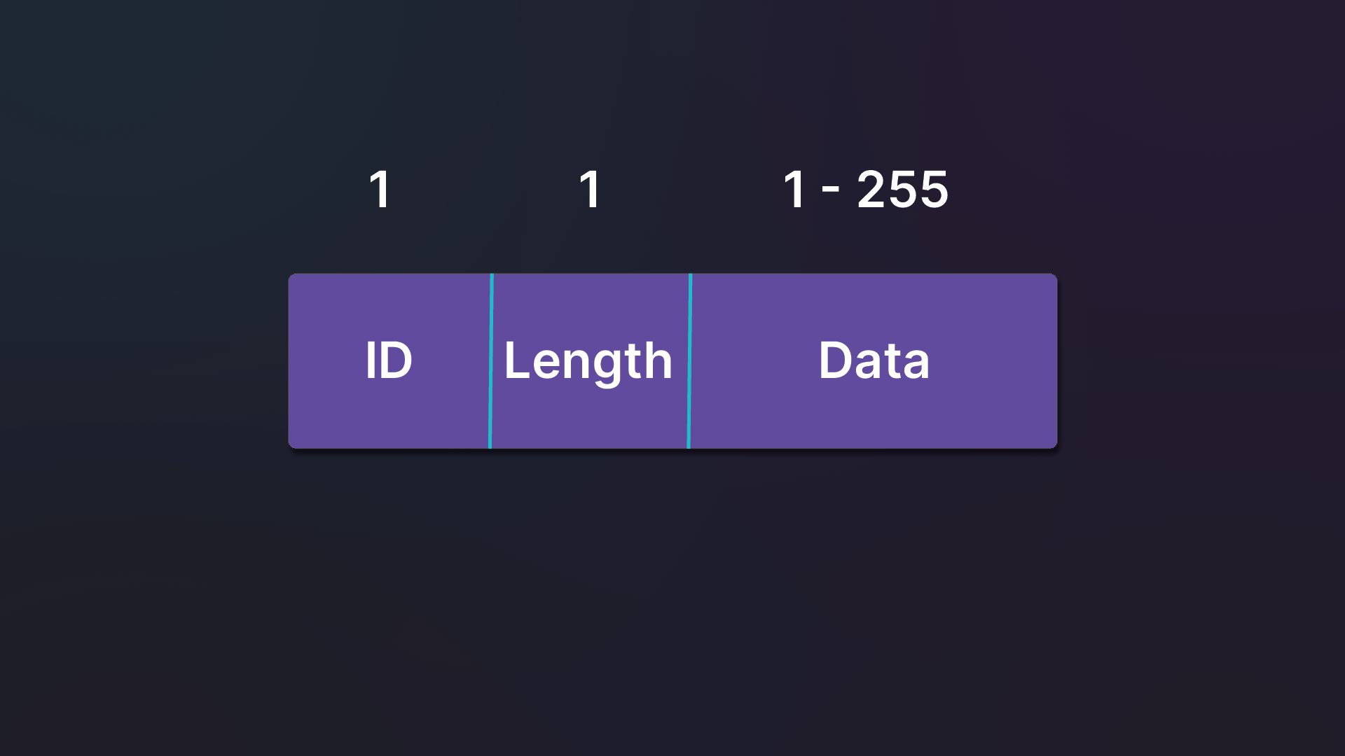
Figure 4: Management frame IE structure
Information Elements are usually arranged in order based on the ID. In special cases, some IDs are shared among multiple items, so their meaning depends also on the first few bytes in the IE's payload. A good example of this is WPA TKIP, where it depends on the first three bytes in the payload. The other special case is the Element ID Extension, which depends on the value of the first byte of its payload. This is used for 802.11ax information among other things.
Although this section is dynamic, some elements such as the SSID will always be present. Figure 5 includes the SSID element, which has an ID of 0. The length of the field is 8 and it is named supafast.
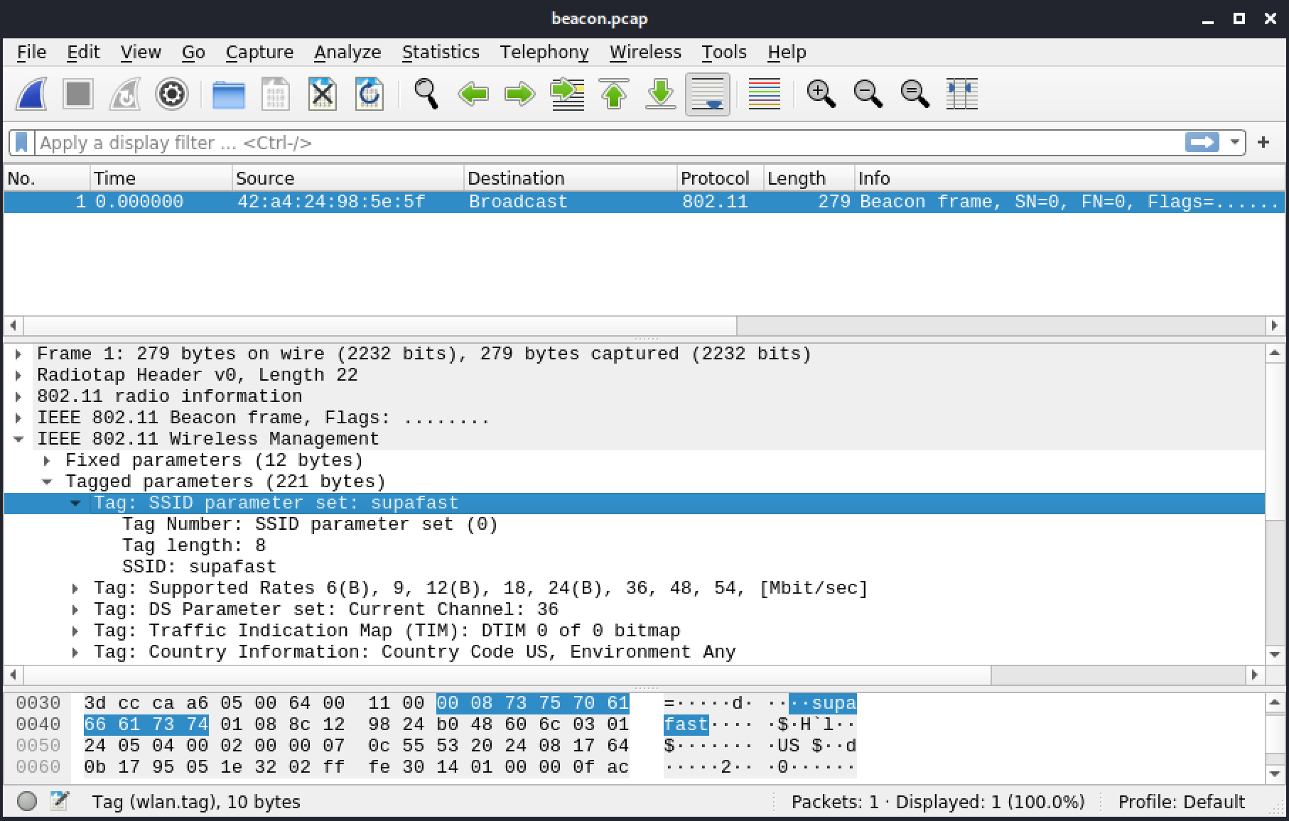
Figure 5: SSID element
Another field to note in the capture is the Supported Rates of the AP. It shows rates of 6 to 54Mbit/s, which, alone, indicates either an 802.11g or 802.11a network.
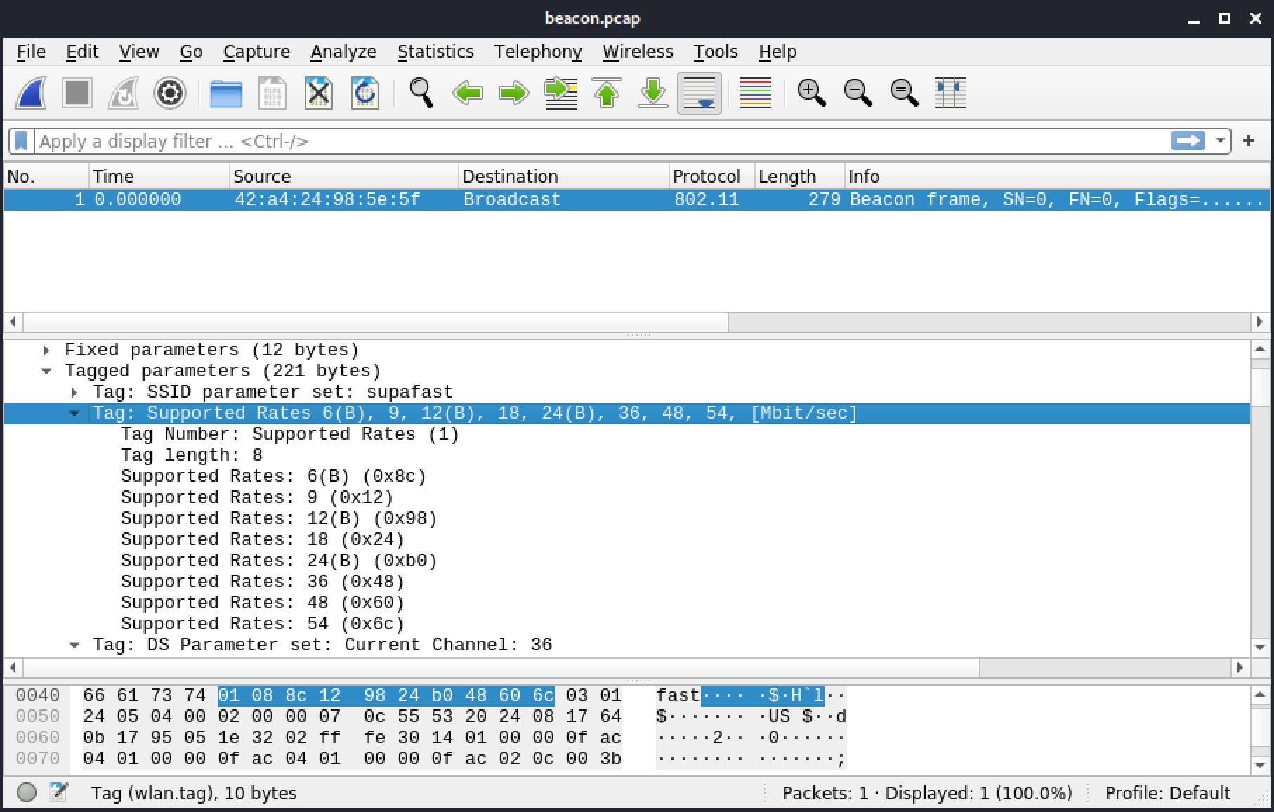
Figure 6: Supported Rates
A 802.11b or mixed 802.11b/g would have these rates between 1 and 11. A mixed 802.11b/g will also have extended supported rates typically between 6 and 54, but this isn't the case in the extended rates below.
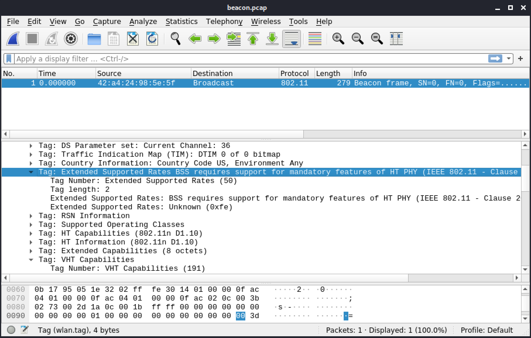
Figure 7: Extended Supported Rates
The channel number, 36, indicates the network is operating in the 5GHz band.
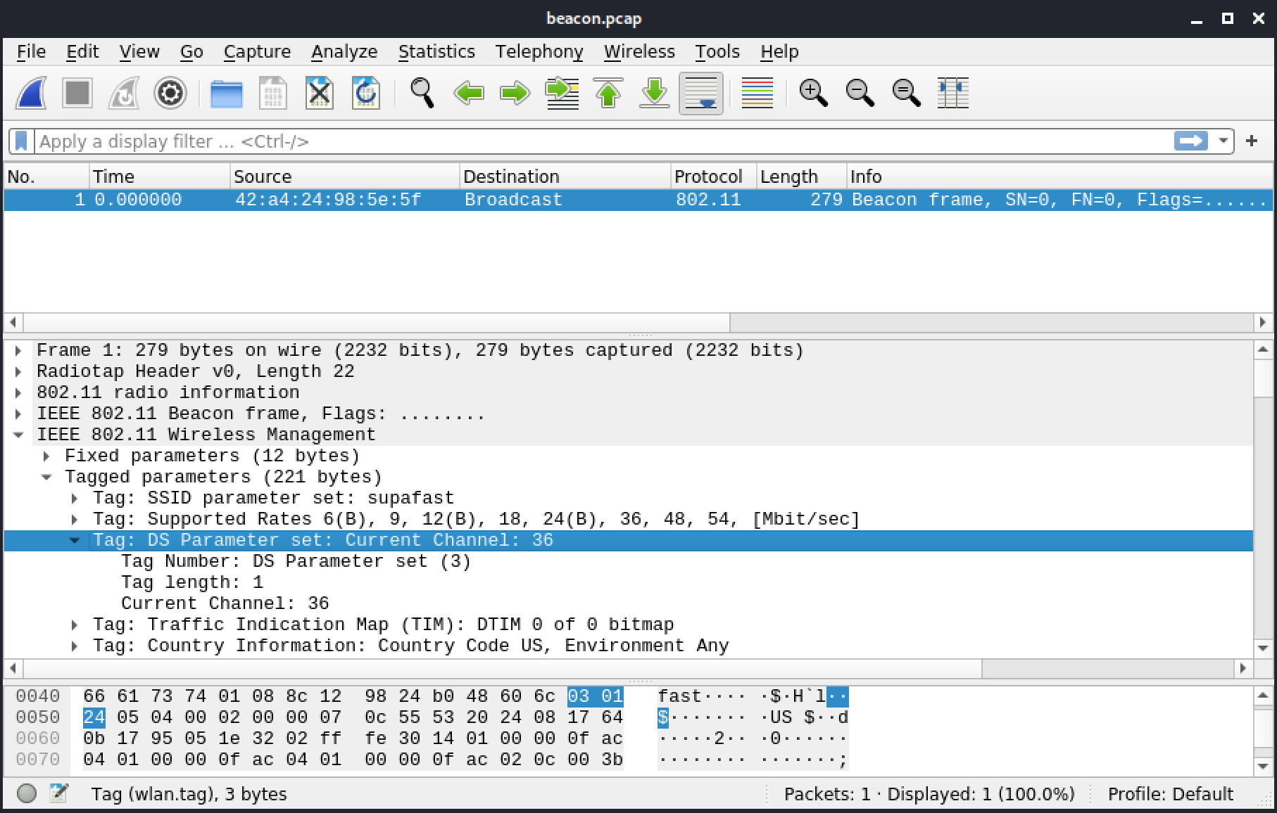
Figure 8: Channel number
The country element indicates the regulatory domain, channels availability, and transmit power. Clients sometimes use it to further improve their compliance. On Linux this is called "beacon hinting".
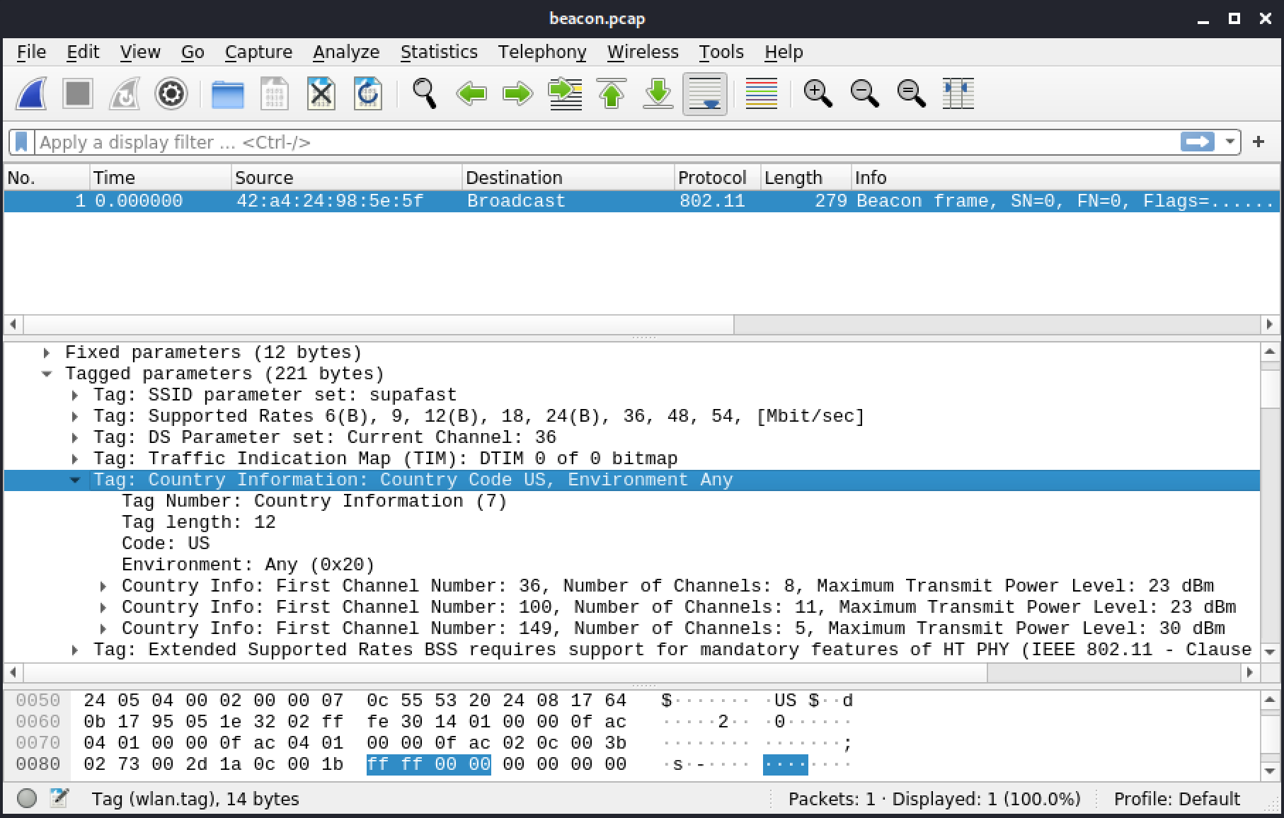
Figure 9: Country information
On this particular AP, the regulatory domain is set to US. It gives a set of channels, as well as maximum transmit power. Eight channels are available at a transmit power of 23dBm, starting at channel 36 (40, 44, 48, 52, 56, 60, and 64). There are 11 channels starting at 100 with 23dBm (104, 108, 112, 116, 120, 124, 128, 136, and 140). There are five channels starting at 149 with 30dBm (153, 157, 161, and 165). The reason why it doesn't give precise channel numbers for every single one is because in the 5GHz band they are always separated by 20MHz, which is 4 channels apart, and they don't overlap.
The HT Capabilities and HT Information elements, indicate whether the AP supports High Throughput (HT), or 802.11n, and include other relevant information.

Figure 10: HT Capabilities and HT Information
Two elements, VHT Capabilities and VHT Operation, indicate the presence of Very High Throughput (VHT), or 802.11ac, and the features supported. Another similarly named field, VHT Tx Power Envelope, helps further improve regulatory compliance.
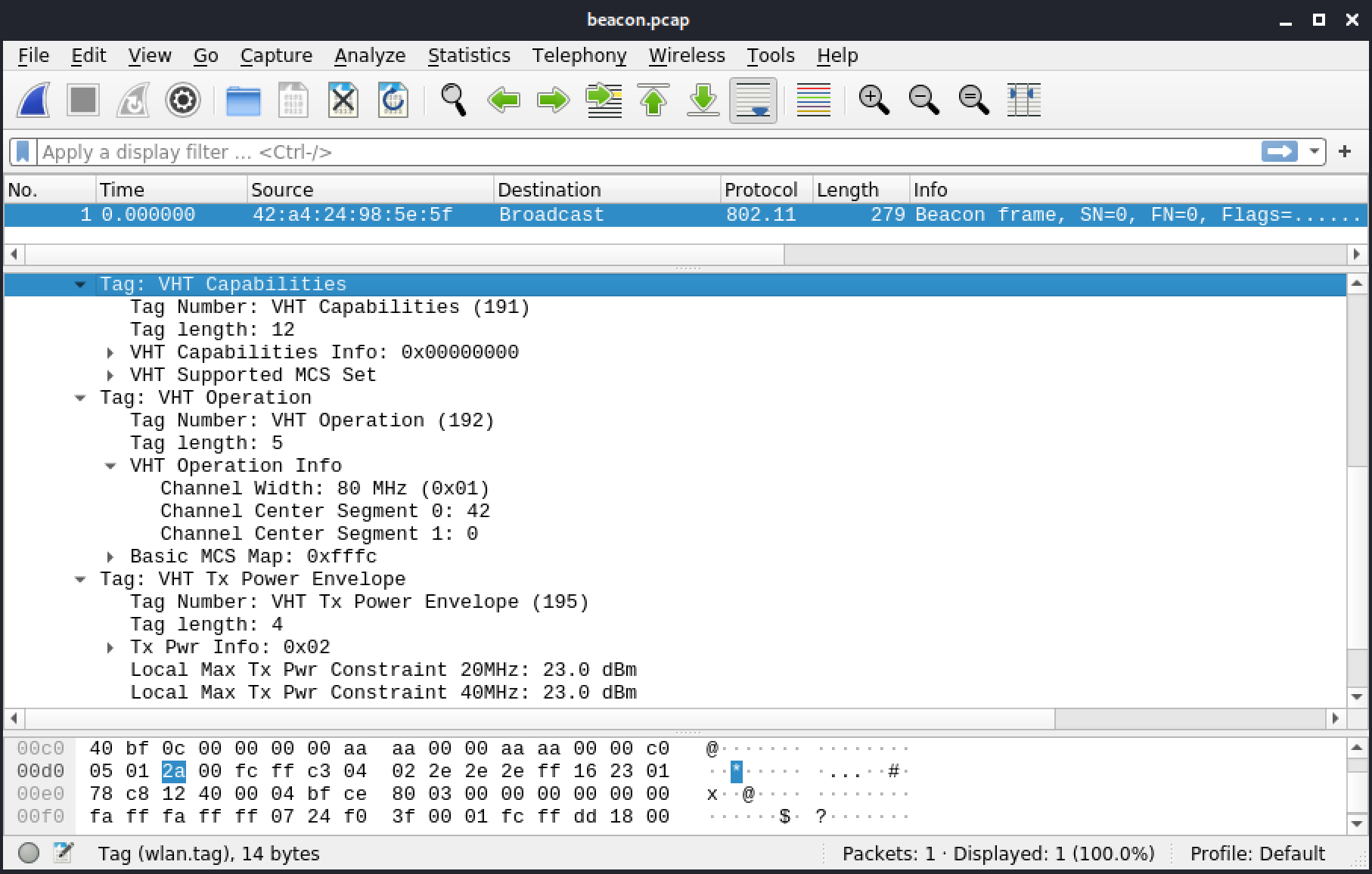
Figure 11: VHT Capabilities and VHT Operation
This AP also supports 80MHz channels, with a center channel at 42. It spans from channels 36 to 48, or 5.170GHz to 5.250GHz. If the second centered segment was filled, it would support 160MHz channels or 80+80MHz. The difference is if it ends up being a contiguous 160MHz or not; 80+80 are two 80MHz channels which aren't next to each other.
Finally, the HE Capabilities and HE Operation elements indicate High Efficiency (HE), or 802.11ax, and the features supported.
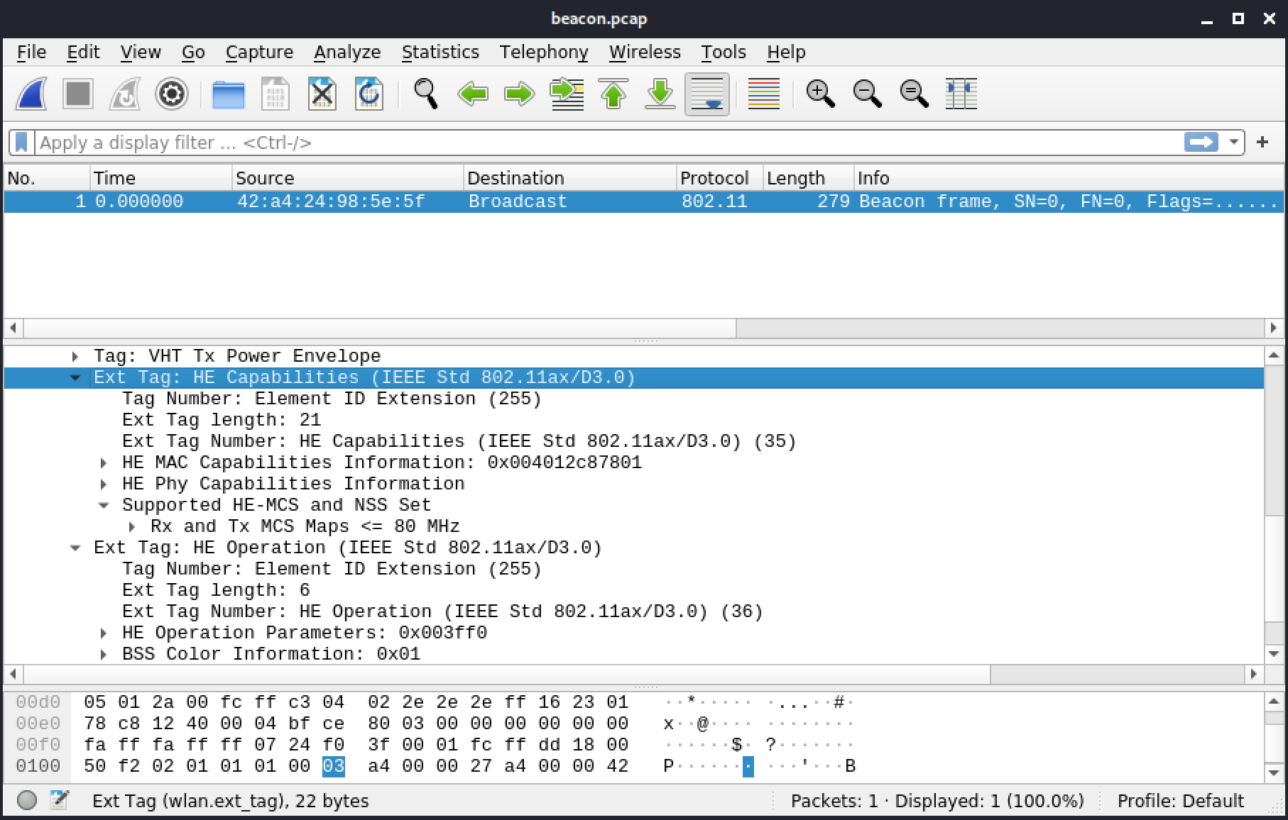
Figure 12: HE Capabilites and HE Operation
The AP supports 80MHz in HE, as indicated by the Rx and Tx MCS Map. It only has one stream, as indicated by the first line in Basic HE-MCS and NSS Set, with rates using MCS 0 to 7, which means up to 360Mbit/s.
5.3.3. Probe
This section includes a reference file, airport-wifi-01_2_3.cap, in the Resources section.
Probe frames are used to scan for existing APs. Probe requests are sent by clients searching for APs, and they are often sent on multiple channels. An AP will answer with a probe response that contains information about itself.
Probe requests may contain specific criteria, including, for example, encryption and rates. APs or ad-hoc (IBSS) nodes will only respond to probe requests that match what they offer. When the Probe request is directed to a specific SSID, only the AP with that SSID will respond.
The structure of probe requests and responses is similar to beacons. Probe request payloads only consist of IEs. The response, which comes from the AP, will contain both the same static and the same dynamic section as the beacon.
A probe request will contain at the very least a SSID IE. It may contain more, depending on the device.
The following capture includes a broadcast probe request.
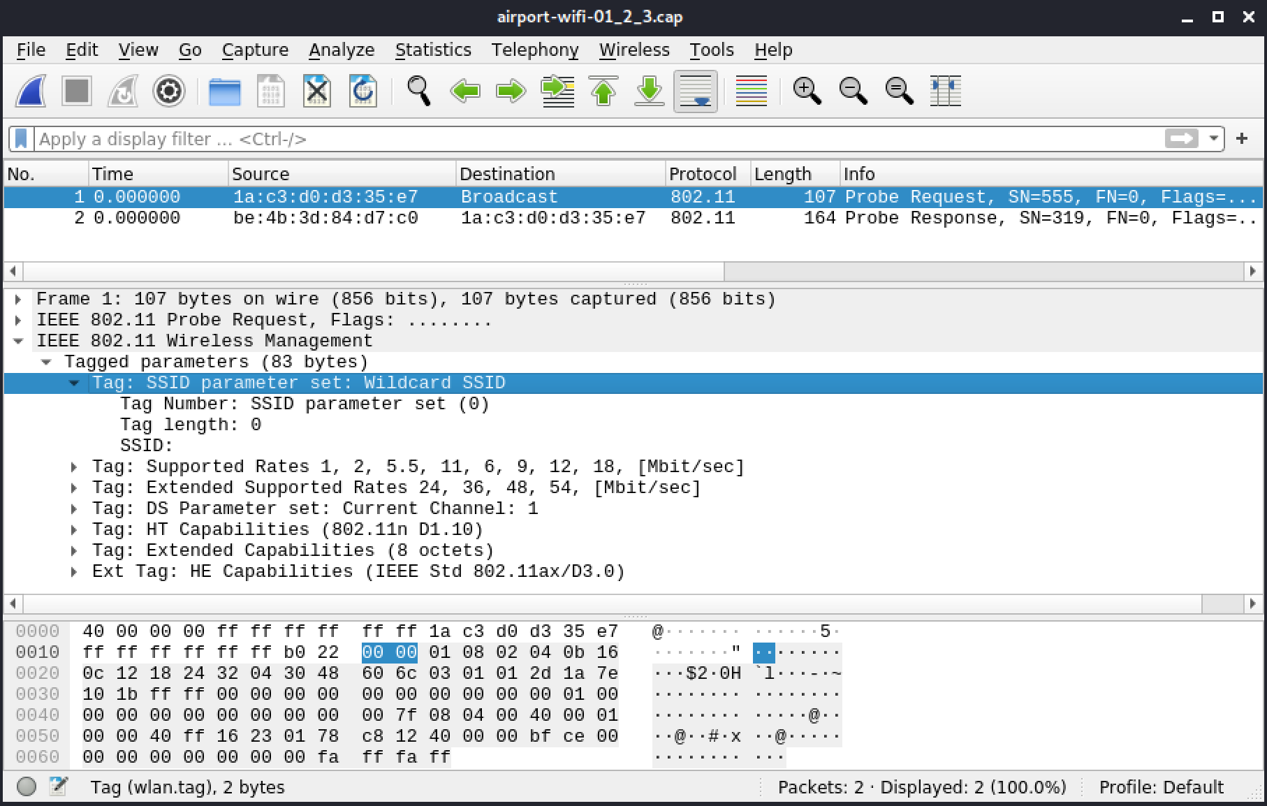
Figure 13: Broadcast Probe Request
A probe response, from the AP, follows the request.
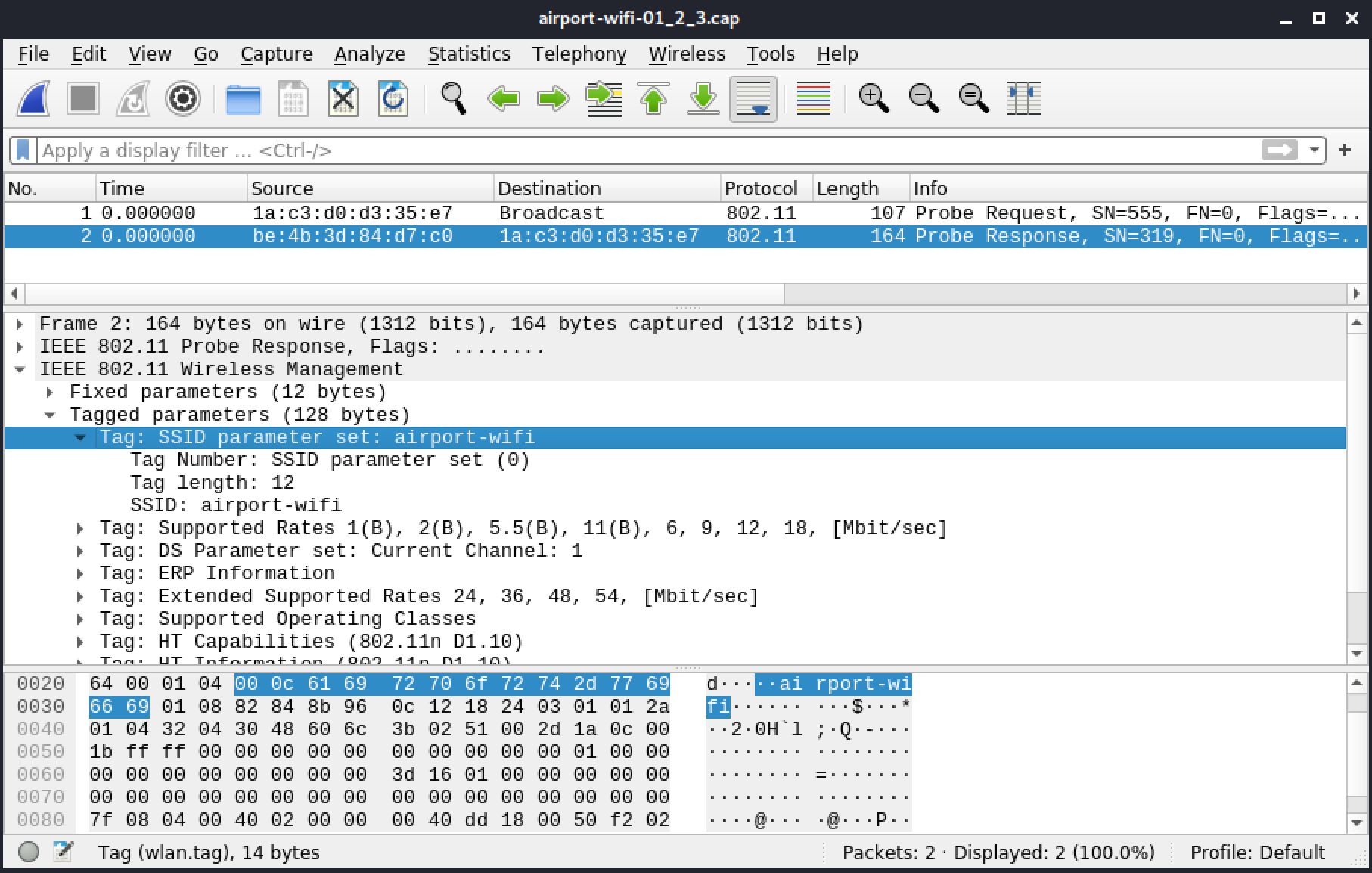
Figure 13: Broadcast Probe Request
5.3.4. Authentication
This section includes a reference file, airport-wifi-01_24_26.cap, in the Resources section.
Authentication frames are used when connecting to an AP. There is no authentication request or response. Both the client and the AP use the same authentication frame.
The payload contains four fields.
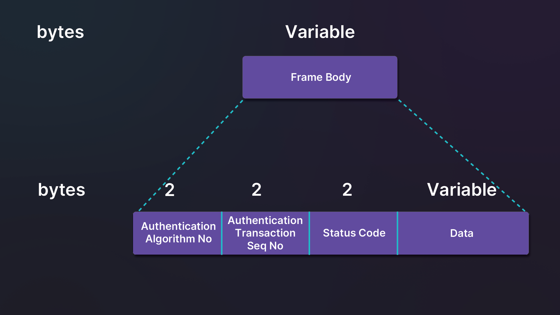
Figure 14: Authentication frame structure
Within an authentication frame, the Authentication Algorithm identifies the type of authentication used. The most common is Open authentication, but we will also encounter Simultaneous Authentication of Equals, which is used with WPA3, and in rare cases, Shared Authentication, which is used with WEP Shared Authentication.
The authentication process consists of several authentication frames (the exact number of frames exchanged can vary). The Authentication Transaction Sequence Number keeps track of the current state of the authentication process and will usually be a value between 1 and 4.
The Status Code indicates success (0) or failure (other values). Other than 0, each value indicates a different type of failure.
Warning
MAC filtering is an after-thought by vendors, and not part of the 802.11 standard. Implementation varies from one vendor to another. When MAC filtering is enabled on the AP and the MAC address of the client is not authorized to connect, the AP may or may not answer. If it does answer, it can either indicate a failure, or success.
Depending on the authentication algorithm and the sequence number, the frame sometimes contain data after all these fields. The meaning of the data in this section depends on the value of the authentication algorithm and the authentication sequence fields.
In the following figure, a client is starting an open authentication phase with an AP.
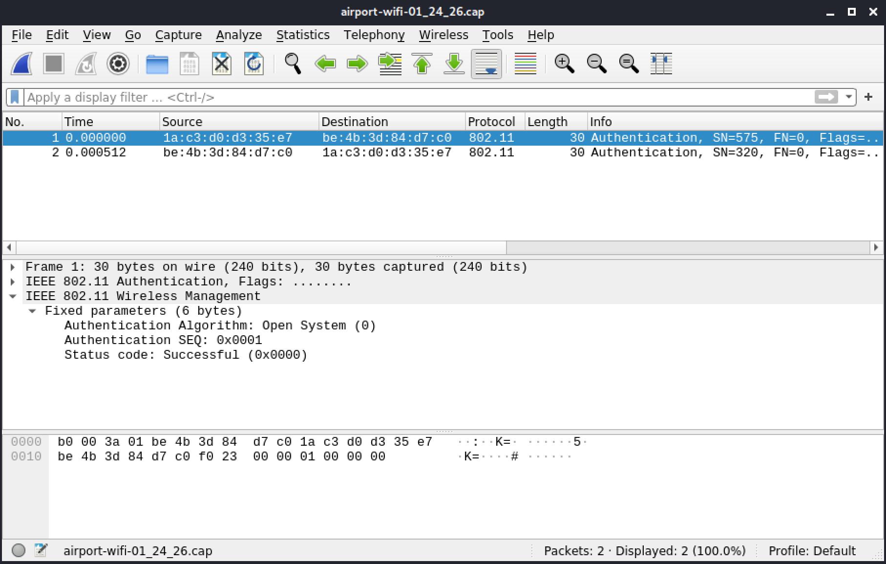
Figure 15: Authentication
The second frame includes the response from the AP.
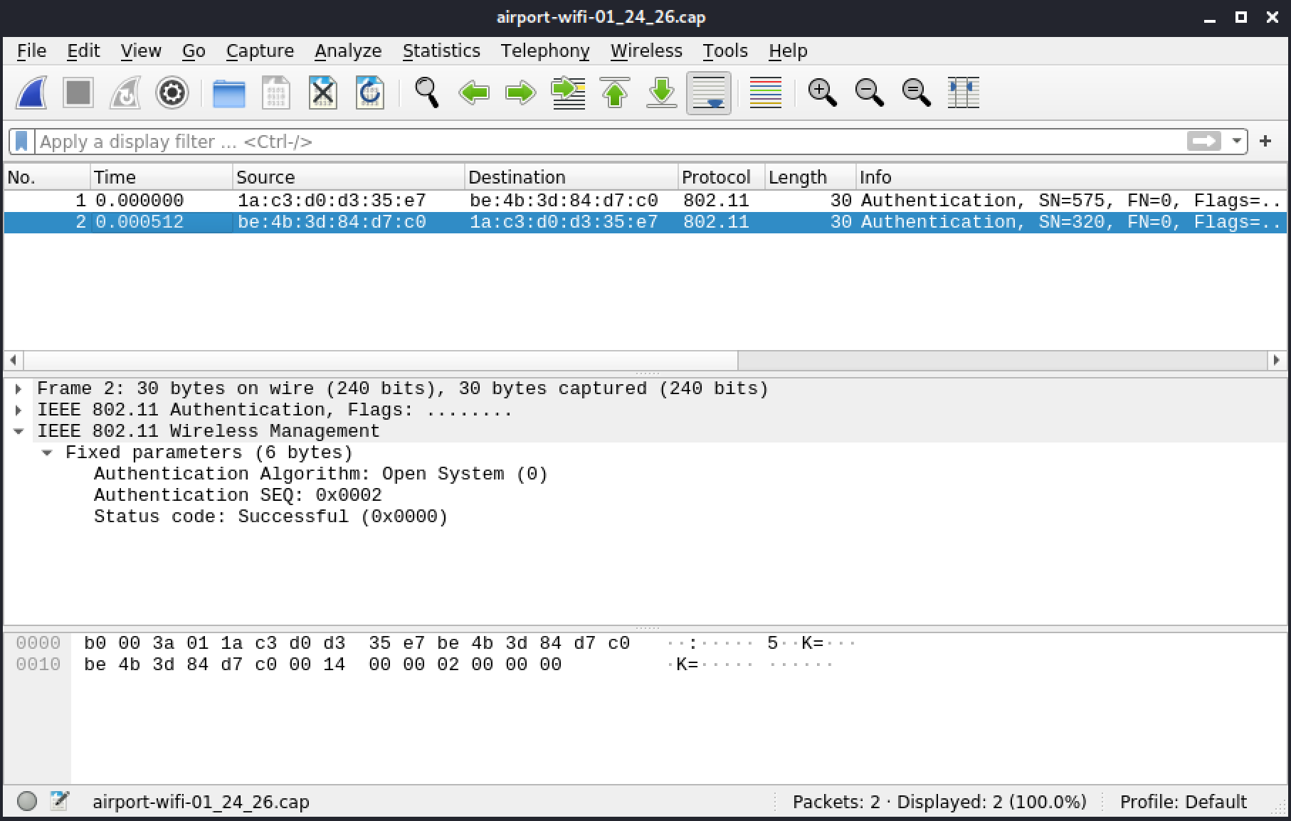
Figure 16: Authentication Response
5.3.5. Association
This section includes a reference file, airport-wifi-01_28_30.cap, in the Resources section.
Association frames are used to connect to an AP and are always preceded by authentication frames. The client sends an association request, which is usually followed by an association response from the AP.
An association request frame has the following structure.
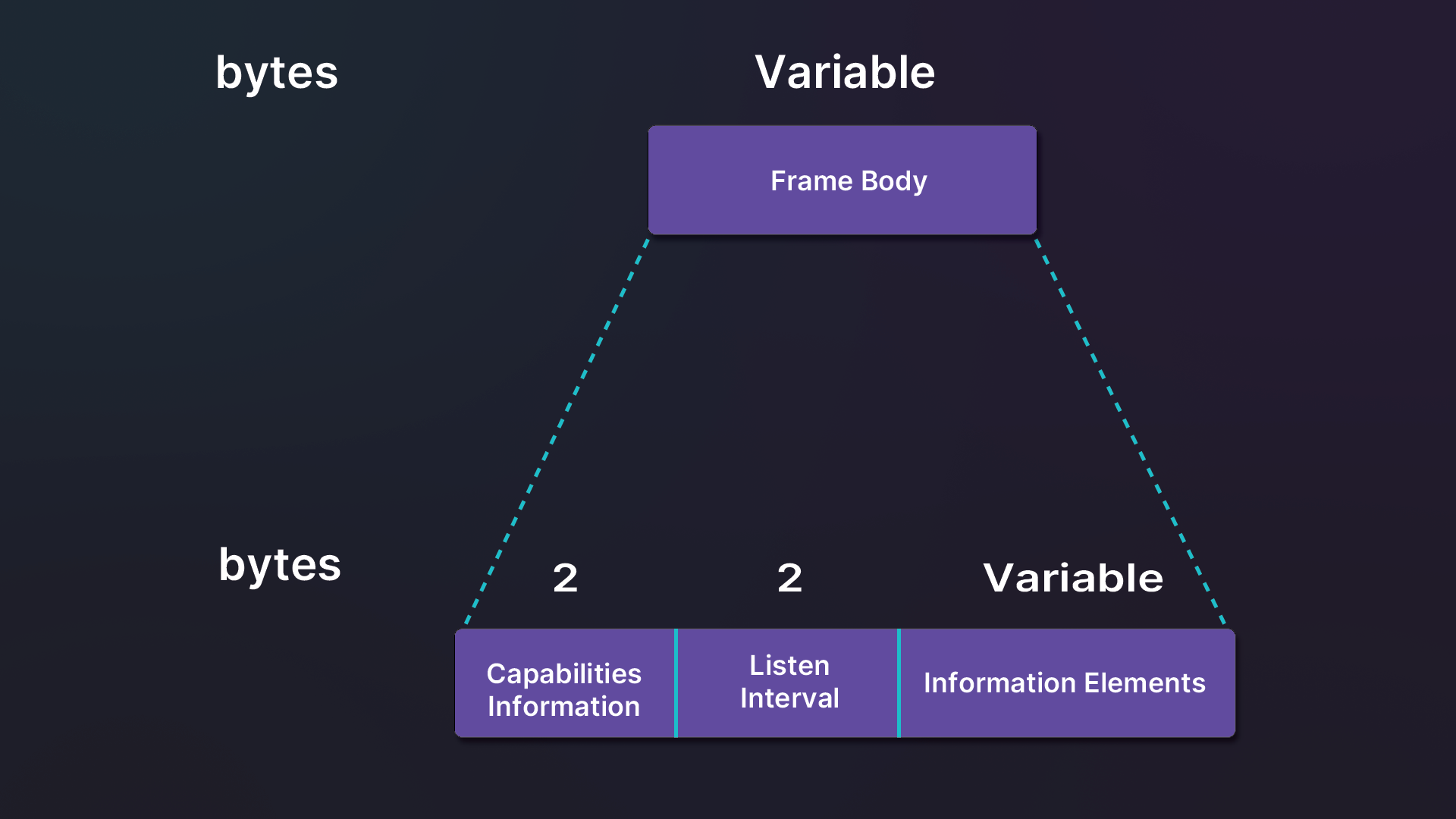
Figure 17: Association request structure
The capabilities are identical to the beacon frame. The listen interval is expressed in TU and indicates how often it will wake up to listen to beacons when in power-save mode. Although it is followed by optional IEs, an SSID IE, along with one of the supported rates field, are required to associate to the AP. When connecting to an AP with encryption, the selected encryption parameters must be specified in this frame as well.
The following figure contains an association request for the "airport-wifi" network.
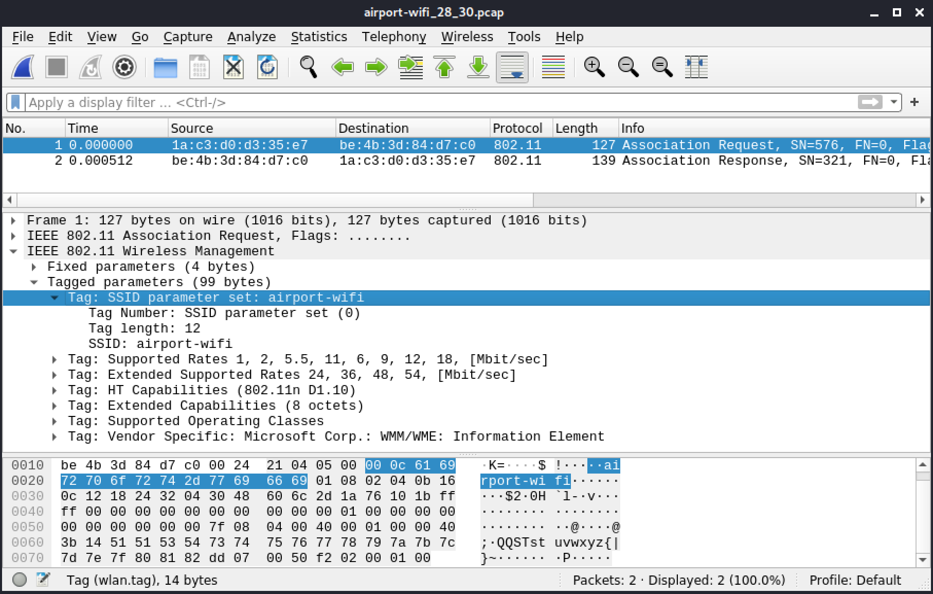
Figure 18: Association Request
APs reject or accept an Association Request with an Association Response.
Warning
When MAC filtering is in place and the MAC address is not authorized, the behavior of the AP can vary. It will either ignore or deny the device.
The Association Response has the following structure.
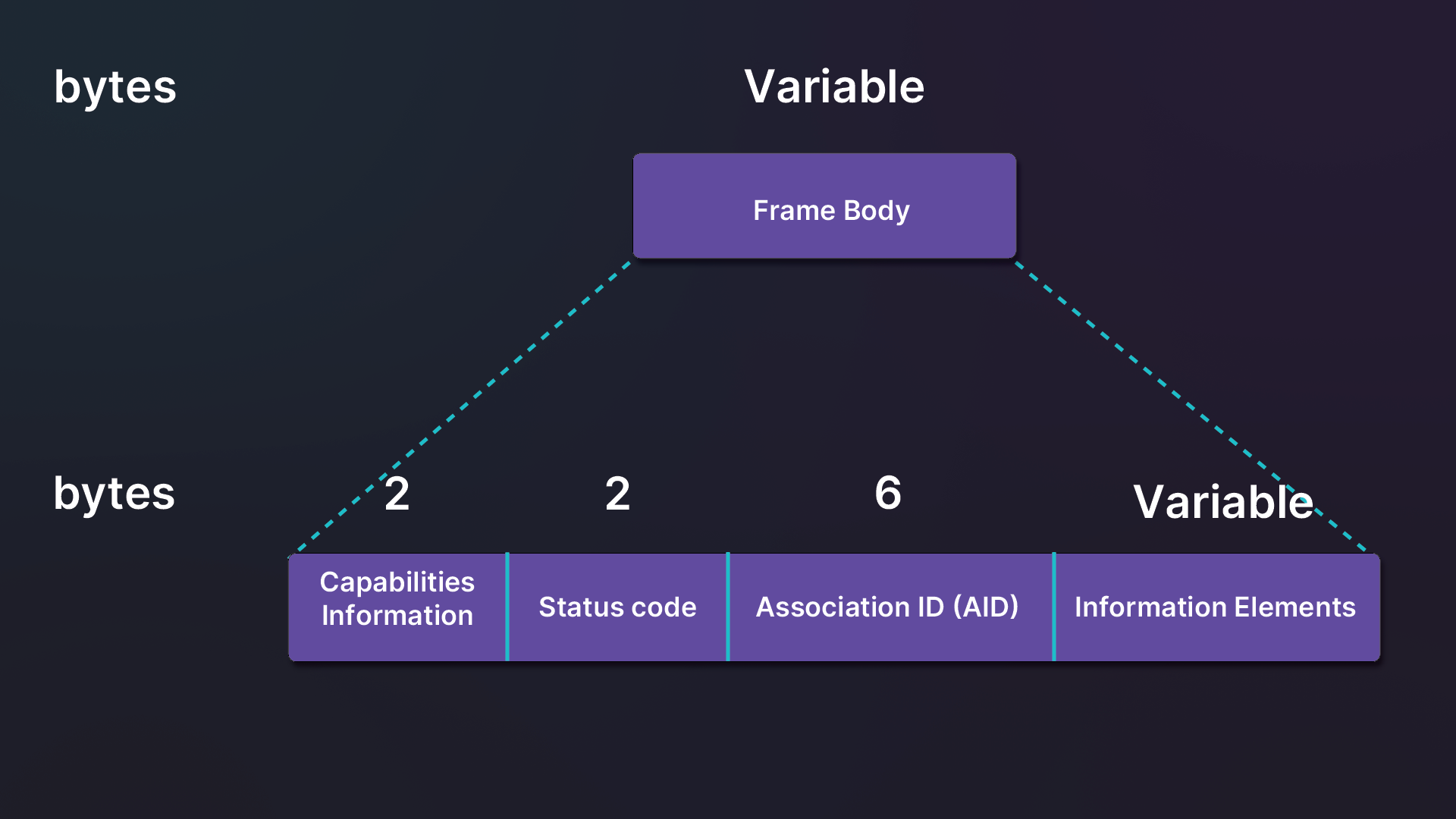
Figure 19: Association response structure
Figure 20 includes a successful association response as indicated by the Status code.
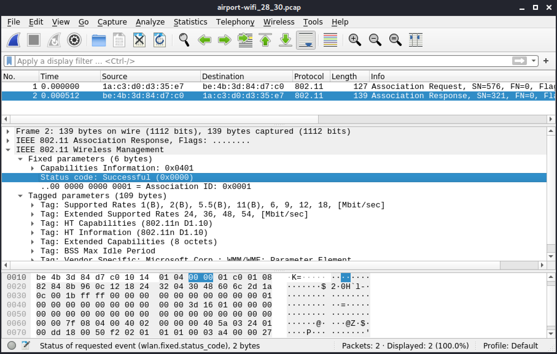
Figure 20: Association Response
5.3.6. Deauthentication
This section includes two reference files:
- Airport wifi pcap
- aireplay-ng pcap
Deauthentication frames invalidate the authentication between a client and an AP. While they are used in attacks, they also occur when a client is disconnecting or when the AP forces the client to reauthenticate for security reasons.
Deauthentication frame structure consists of one 2-bytes long field in the frame body. This field, the Reason Code, indicates the reason for the deauthentication.
In the following frame, the client is disconnecting and uses a reason code 3 ("Deauthenticated because sending STA is leaving").
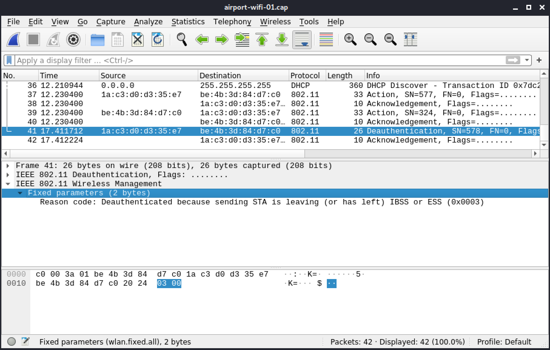
Figure 21: Reason Code Deauthenticated
In the next example, the frame was sent by aireplay-ng to the BSSID 00:89:6e:1a:43:90. It uses the reason code 7 ("Class 3 frame received from nonassociated client").
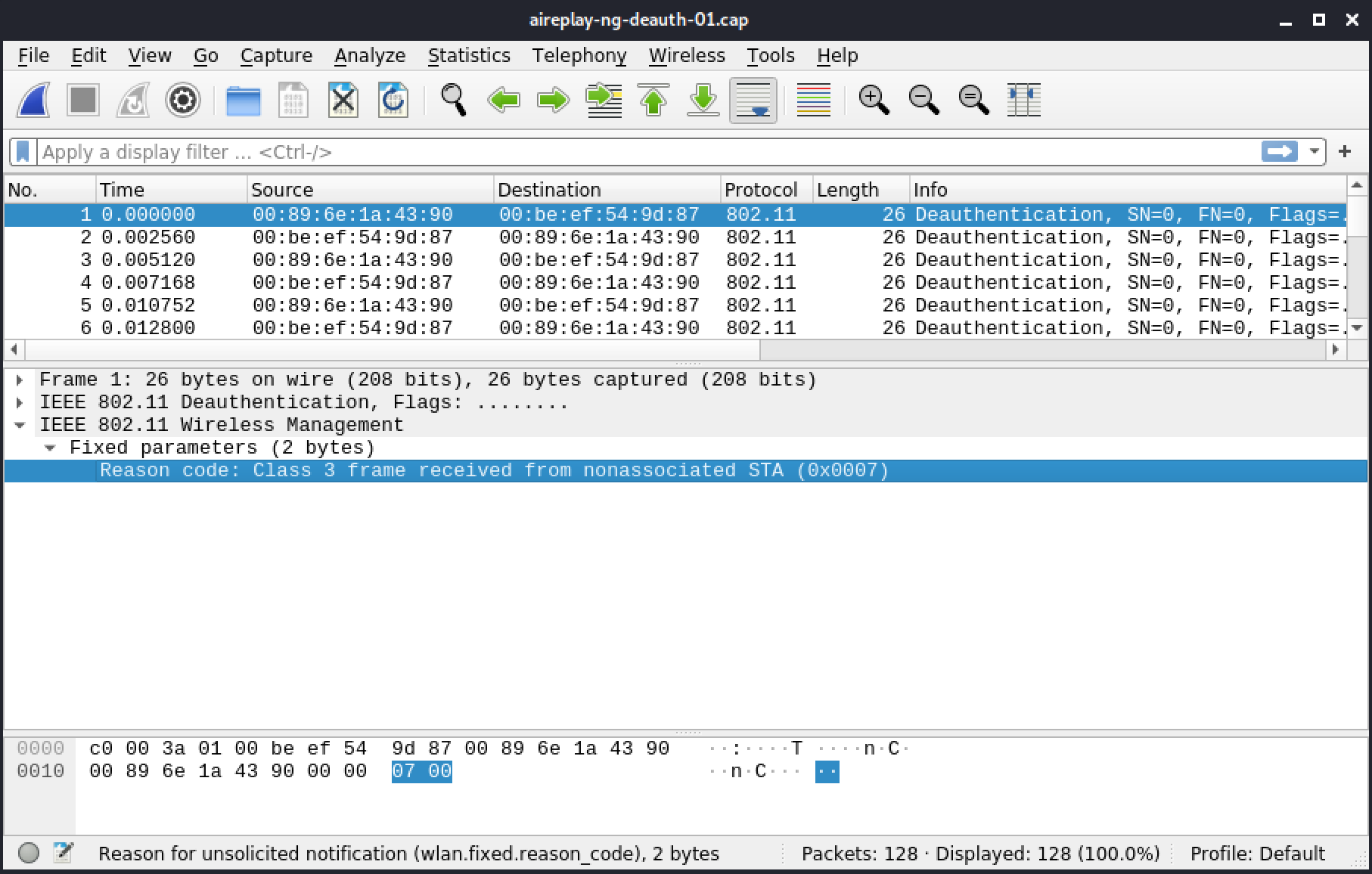
Figure 22: Reason code
AP and clients normally send one deauthentication, a large amount of deauthentication frames usually indicates an attack in progress.
5.3.7. Control Frames
Control frames help to deliver data frames as well as other unicast frames. They need to be heard reliably, so they are short and sent at a low rate. The following table shows the different types of control frames.
| Subtype | Field Description |
|---|---|
| 0-6 | Reserved |
| 7 | Control Wrapper |
| 8 | Block ACK Request |
| 9 | Block ACK |
| 10 | PS-Poll |
| 11 | RTS |
| 12 | CTS |
| 13 | ACK |
| 14 | CF End |
| 15 | CF End + CF-ACK |
Table 4 - Control frames subtypes
Let's go over some of the more common control frame subtypes.
5.3.8. ACK
This section includes a reference file, ack.pcap, in the Resources section.
An ACK frame tells the sending client that the frame was received correctly. These frames are sent for each unicast (directed to a specific device) frame sent.
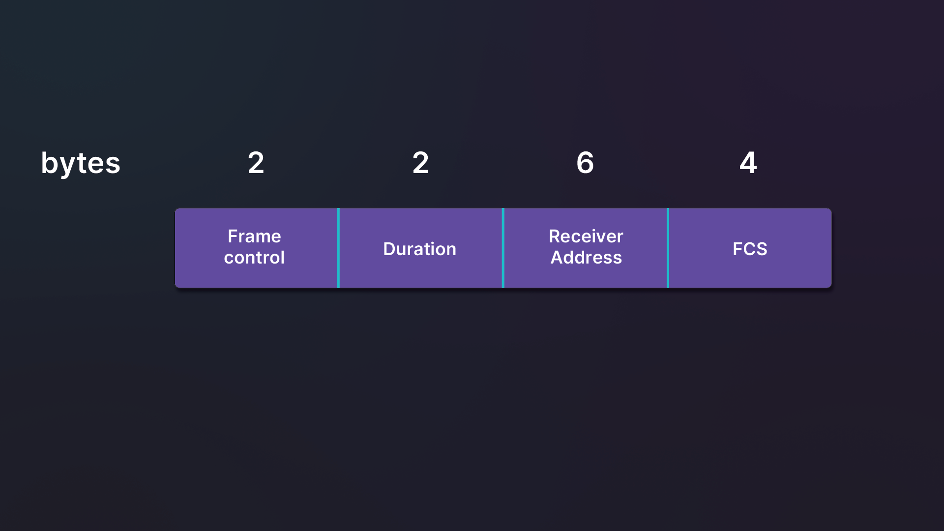
Figure 23: ACK Frame diagram
We can open an ACK frame in a Wireshark capture to inspect it more closely.
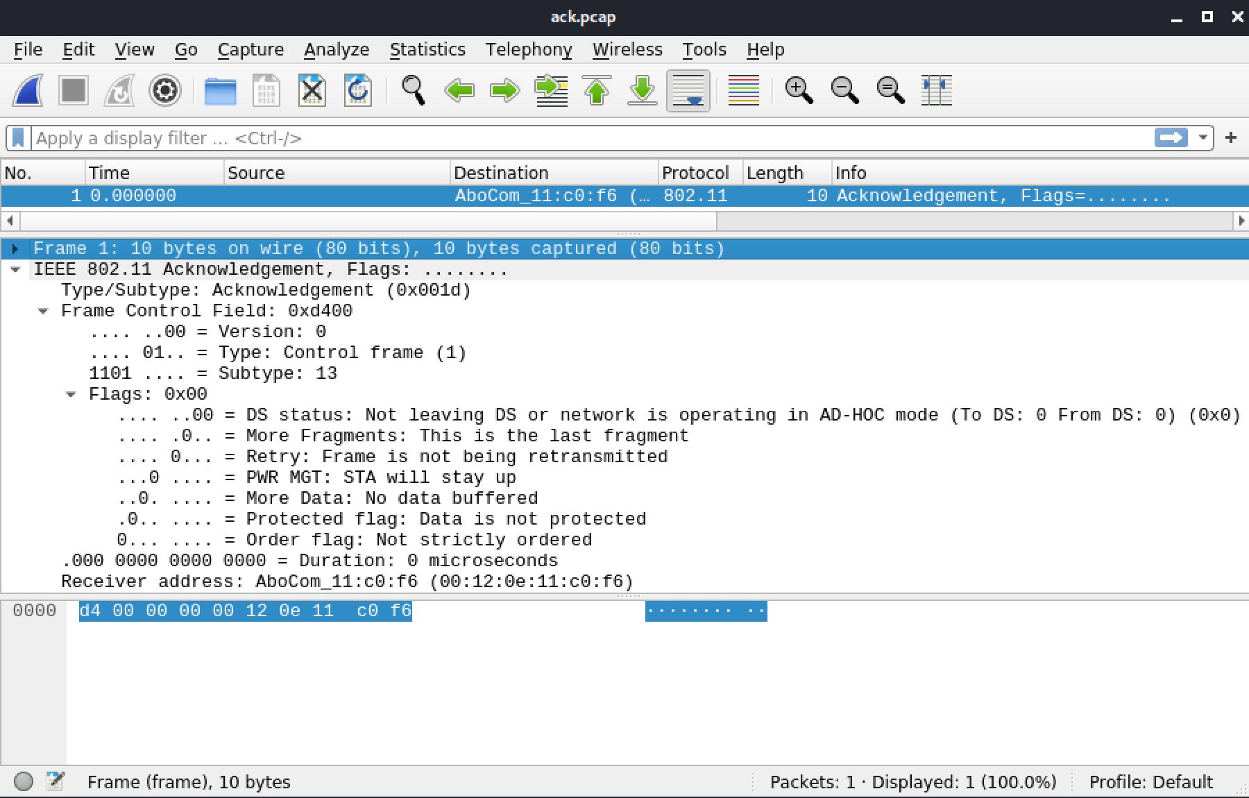
Figure 24: ACK Frame in Wireshark
The ACK frame has a Type field set to 1, which means it is a control frame. The ACK Subtype field is 13.
Block ACK allows one to disable ACK for a certain number of frames and then acknowledge them, which improves throughput. They contain a bitmap of the fragments and each bit represents the status of one of them (ACK/NACK).
5.3.9. RTS/CTS
This section includes a reference file, rts-cts.pcap, in the Resources section.
This section includes a reference file.
RTS/CTS is a supplement to the CSMA/CA mechanism that helps in reducing collisions. It adds overhead to the wireless communication, because additional frames have to be added before and after the communication. Figure 25 illustrates the process.
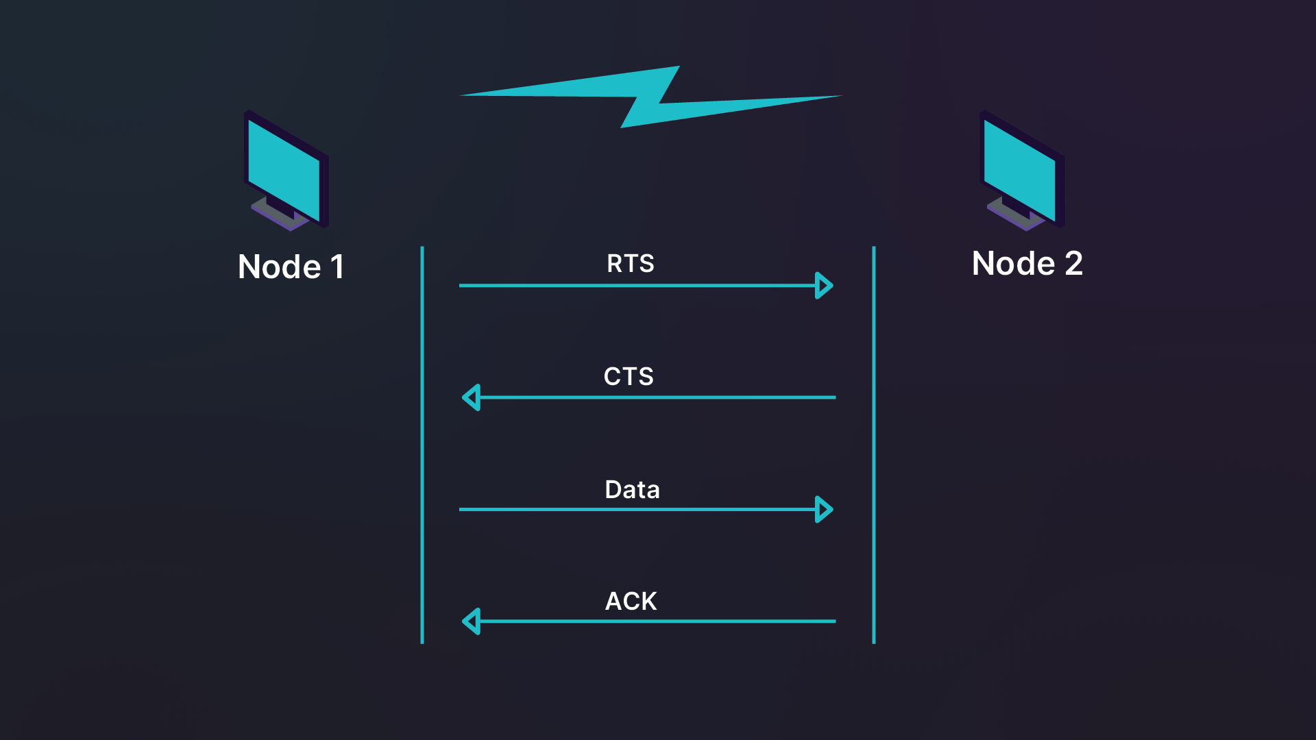
Figure 25: RTS/CTS communication sequence
In Figure 25, Node 1 wants to communicate with Node 2, which can be either an AP or a client.
First, Node 1 sends a "Request to Send" to Node 2. If there was no collision and the request is accepted, Node 2 sends a "Clear to Send" to Node 1 telling it to proceed. Other devices in the surroundings hearing the CTS wait as well. Next, Node 1 sends its data. The data is acknowledged with an ACK frame by Node 2. If the data send fails, no ACK frame is sent.
Let's review the RTS frame structure, which has a length of 20 bytes.
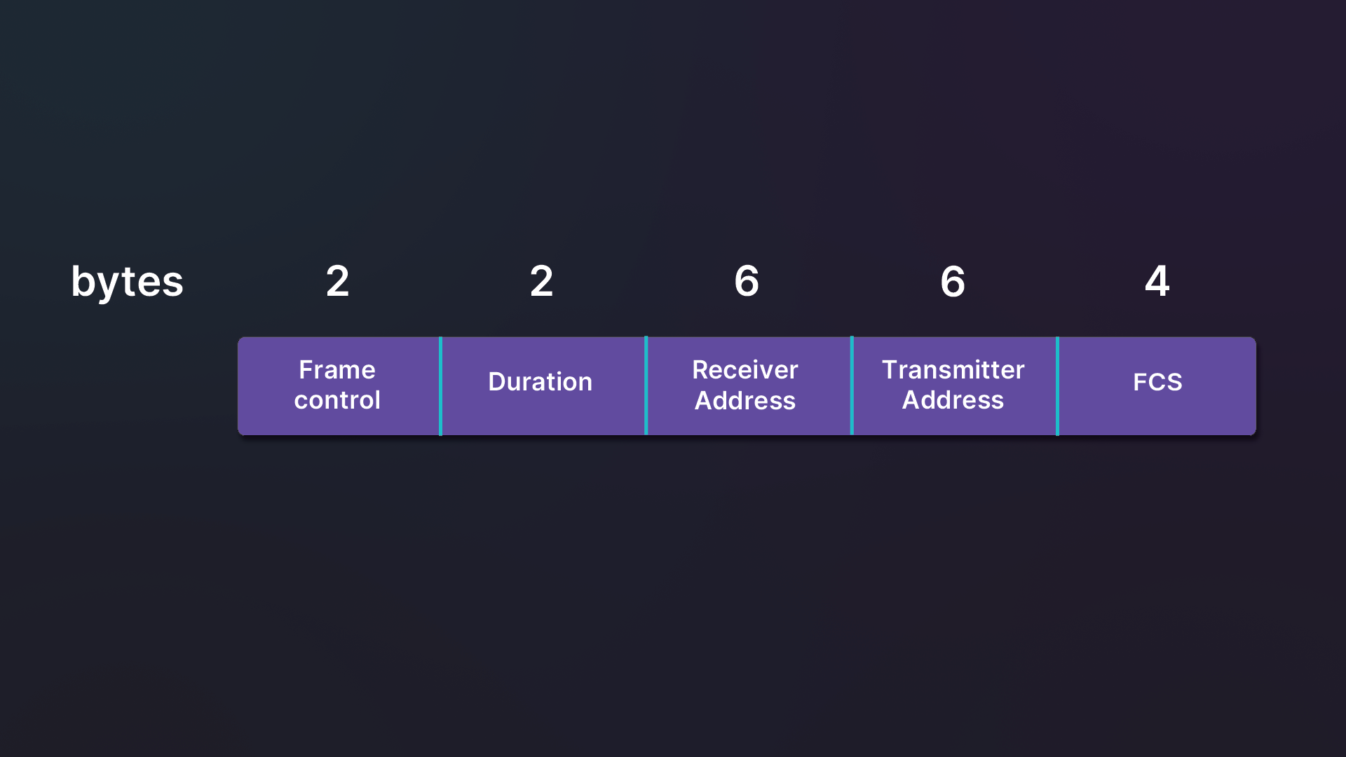
Figure 26: RTS frame structure
By comparison, a CTS frame has the same length (14 bytes) and structure as an ACK frame.
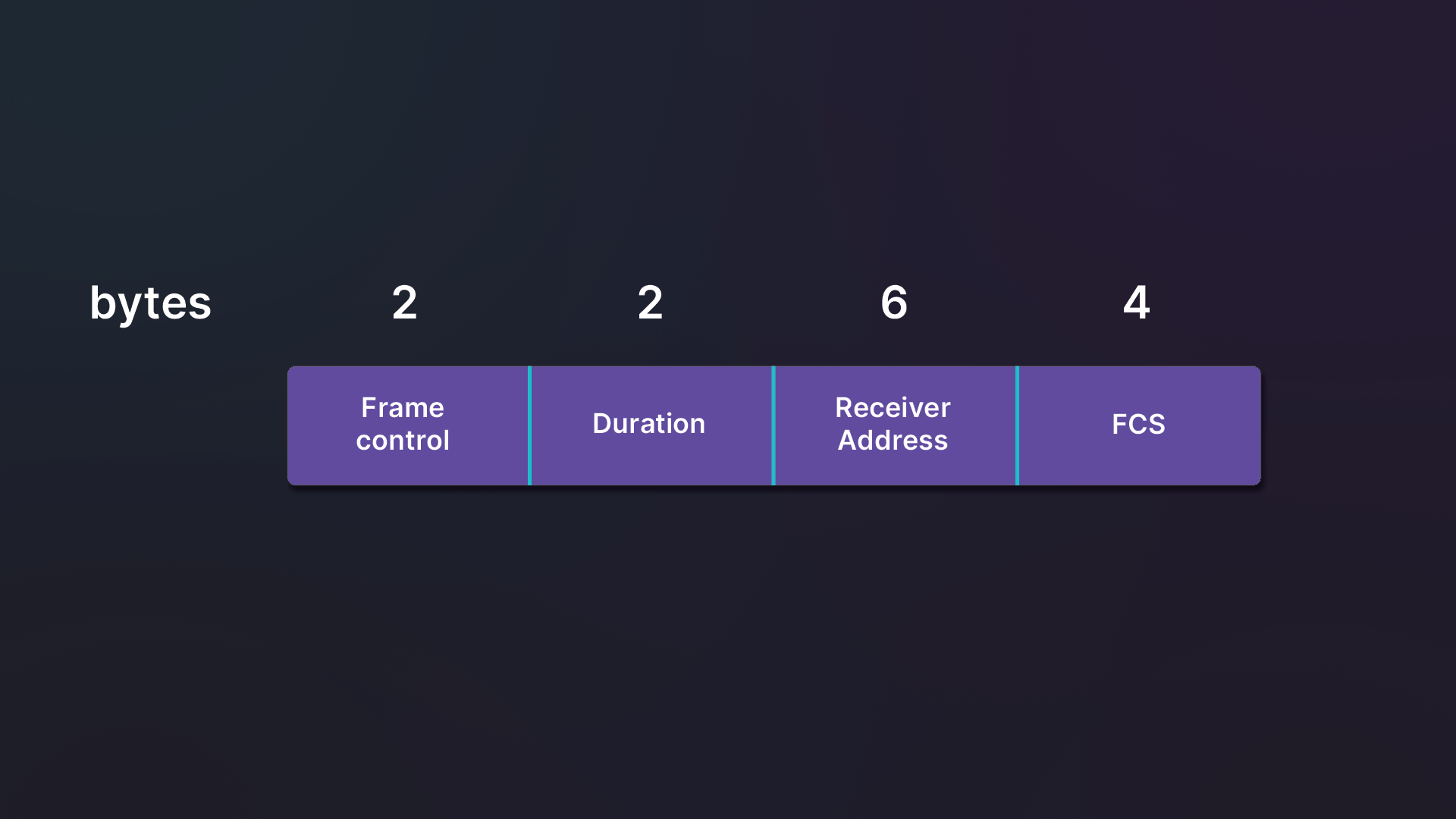
Figure 27: CTS frame structure
Figure 28 includes the entire RTS/CTS sequence in action.
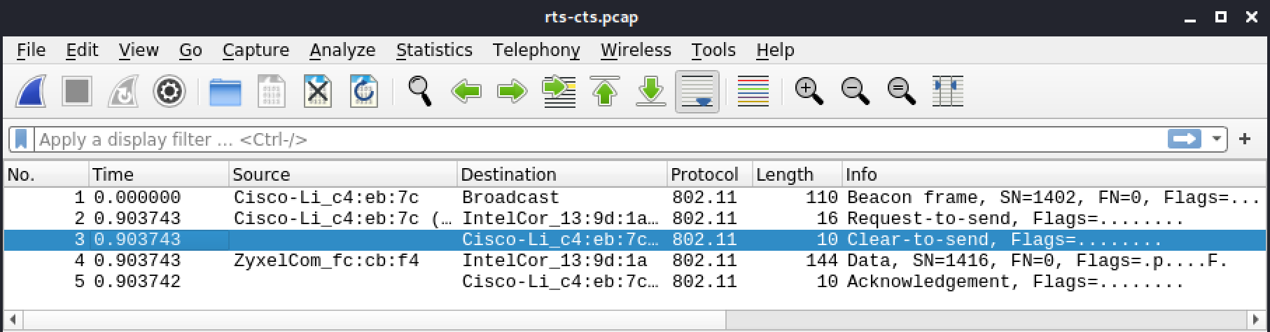
Figure 28: The RTS/CTS sequence in Wireshark
Let's review this capture frame-by-frame to start getting a better understanding of how this transaction takes place.
In the second frame, the AP sends a RTS to the client. Notice that the frame Type is 1 (Control frame) and the Subtype is 11 (RTS).
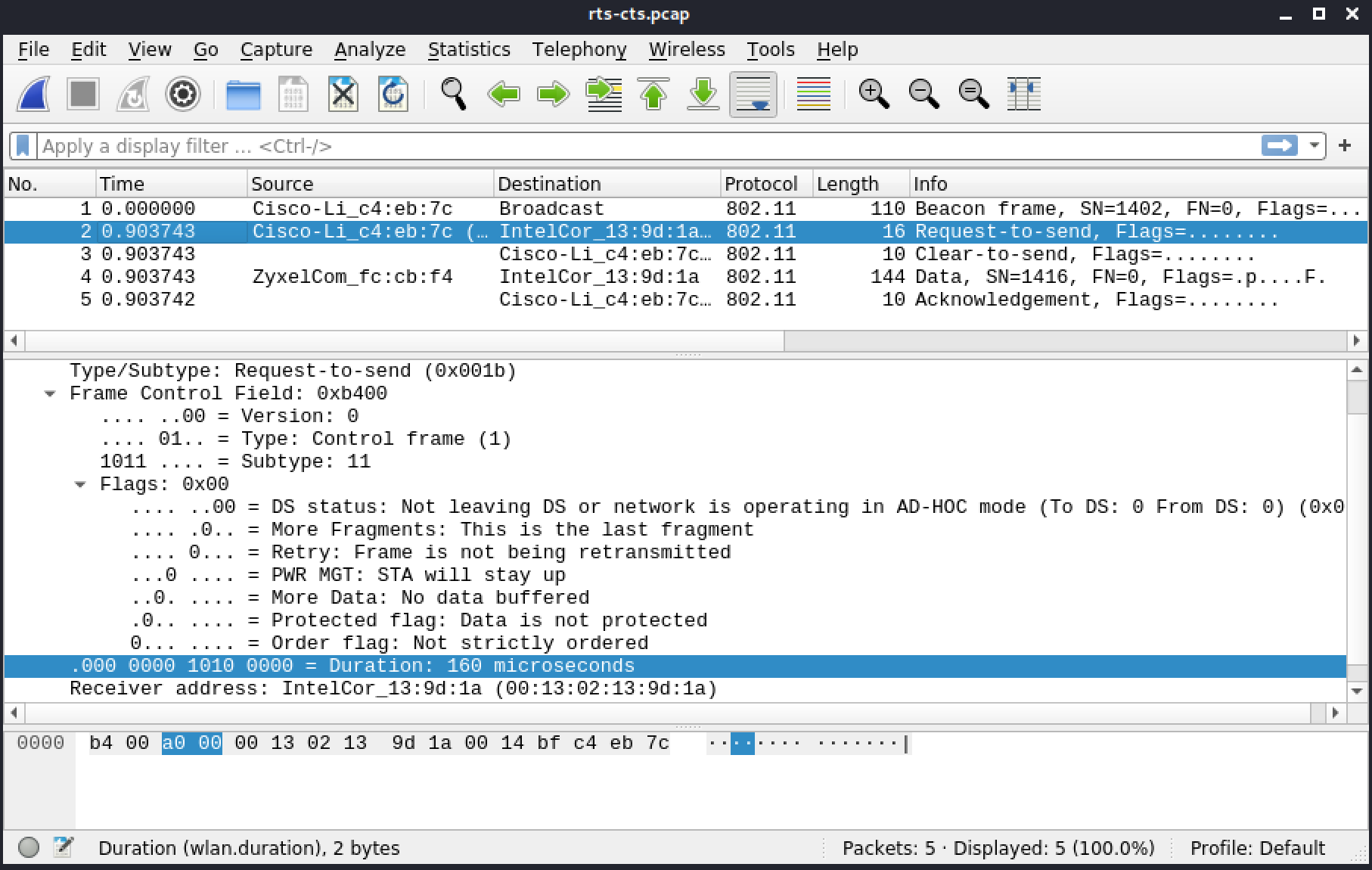
Figure 29: The RTS/CTS sequence in Wireshark - RTS
In the following frame, the client responds to the AP with CTS. The Subtype of the frame is 12 (CTS).
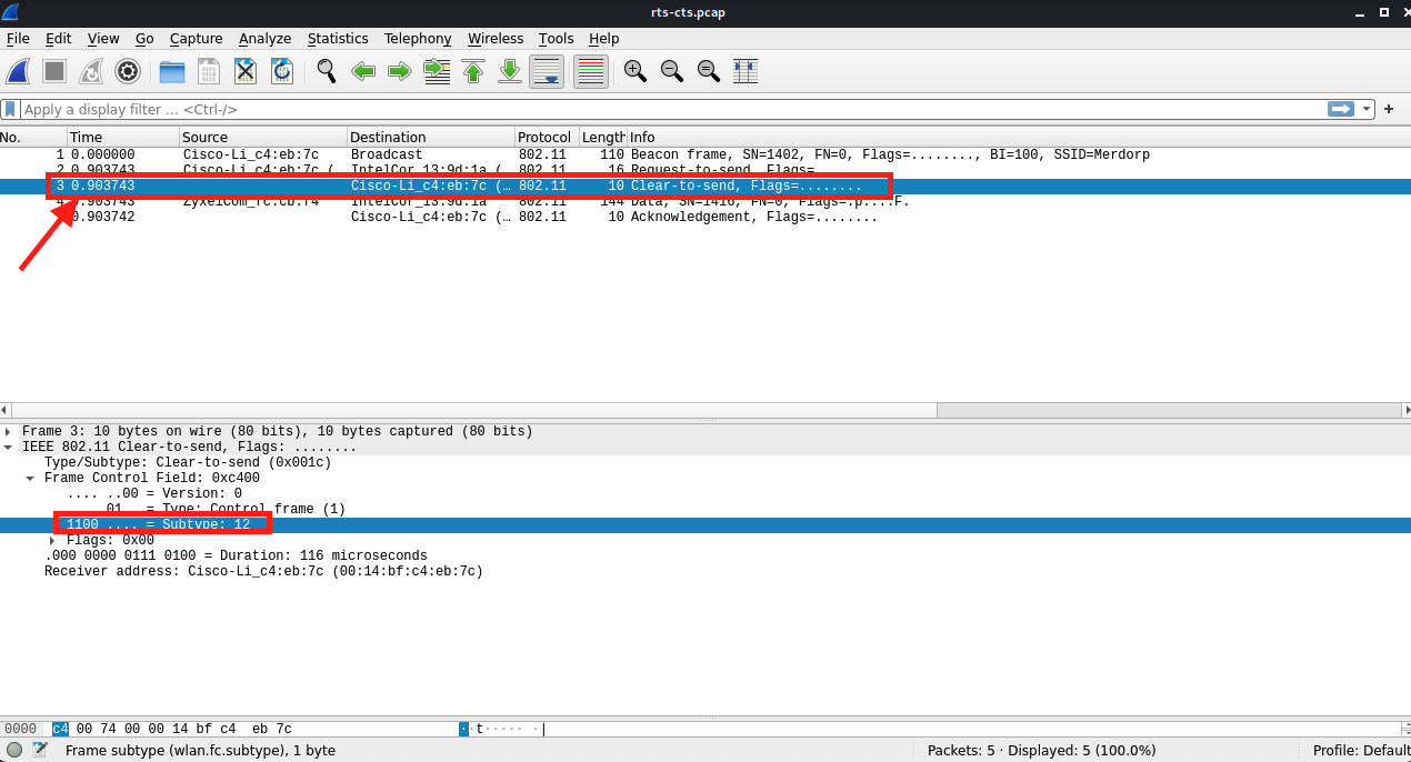
Figure 30: The RTS/CTS sequence in Wireshark - CTS
After it receives a CTS message from the client, the AP sends a data frame from the internal network.
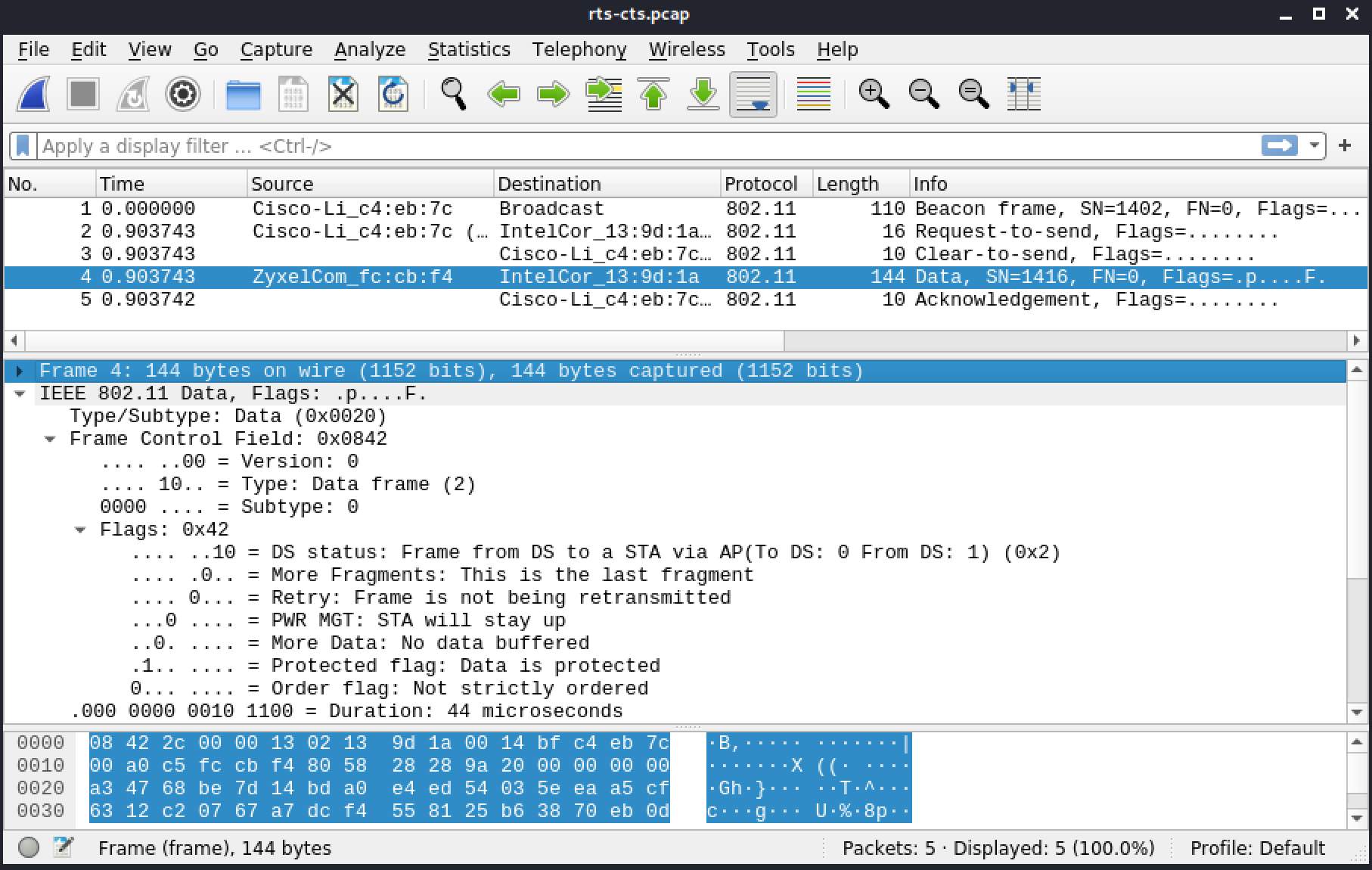
Figure 31: The RTS/CTS sequence in Wireshark - Data frame
Once it has successfully received the data frame, the client sends an ACK (Subtype 13) back to the AP.
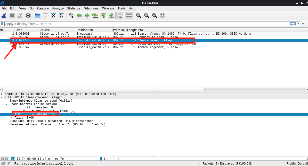
Figure 32: The RTS/CTS sequence in Wireshark - RTS - ACK
In some instances, devices use CTS-to-self protection mechanism before sending data. As mentioned earlier, all other devices hearing CTS will hold before transmitting. The amount of time to wait is specified in this frame's duration field, displayed in Figure 31. As a result, some devices send a CTS before their transmission in improve the likelihood of a successful transfer.
5.3.10. Data Frames
There are a number of different types of data frames, most of which are used to carry data between devices. The following table shows the different types.
| Subtype | Field Description |
|---|---|
| 0 | Data |
| 1 | Data + CF ACK |
| 2 | Data + CF Poll |
| 3 | Data + CF ACK + CF Poll |
| 4 | Null Function (No Data) |
| 5 | CF ACK (No Data) |
| 6 | CF Poll (No Data) |
| 7 | CF ACK + CF Poll (No Data) |
| 8 | QoS Data |
| 9 | QoS Data + CF ACK |
| 10 | QoS Data + CF Poll |
| 11 | QoS Data + CF ACK + CF Poll |
| 12 | QoS Null (No Data) |
| 13 | Reserved |
| 14 | QoS CF Poll (No Data) |
| 15 | QoS CF ACK + CF Poll (No Data) |
Table 5 - Data frames subtypes
The most common data frames are Data (subtype 0), Null Function (subtype 4), and their equivalent with QoS (subtypes 8 and 12 respectively).
QoS data frames are used when prioritizing traffic sensitive to delays, such as voice or video. They contain a QoS Control field before the payload.
5.3.11. Data
This section includes a reference file, airport-wifi_34.pcap, in the Resources section.
Let's examine a DHCP request (UDP) captured on an open network. It happens to be a QoS data frame.
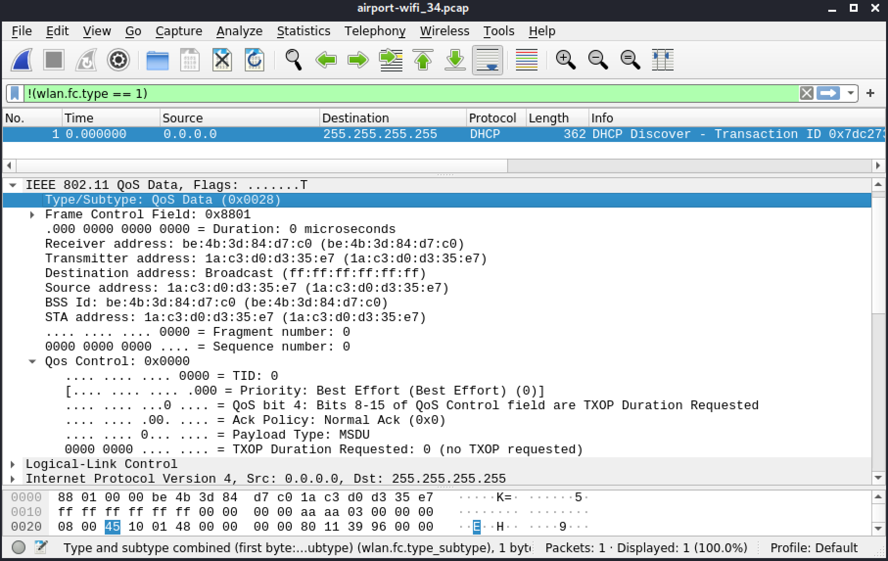
Figure 33: QoS Data
5.3.12. Null Data
This section includes a reference file, null-data-packet.pcap, in the Resources section.
Null frames consist only of MAC headers and a FCS. Clients use them when they are going into power-saving mode. This is the case in Figure 33, where we note that the power management (PWR MGT) bit is set.
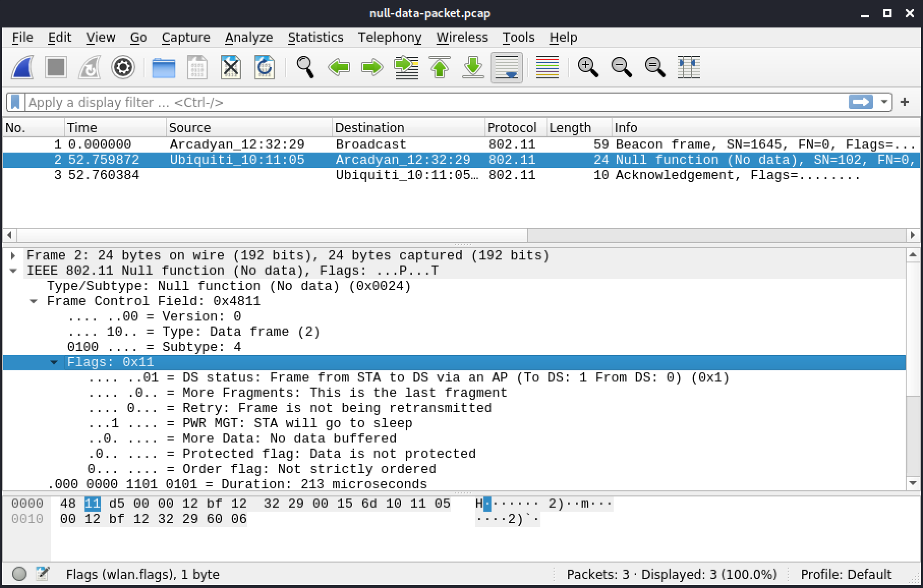
Figure 33: Null frame sent from a client
When the client exits power-saving mode, it will send the same frame with the power management bit reset. The AP will send the client any buffered frames that are waiting.
5.4. Interacting with Networks
Now that we've spent some time exploring the common frames used on networks, let's discuss the steps required for connect to and then transmit data on a wireless network. We will also compare a few different types of network encryption.
We'll begin with the steps of connecting to a wireless network.
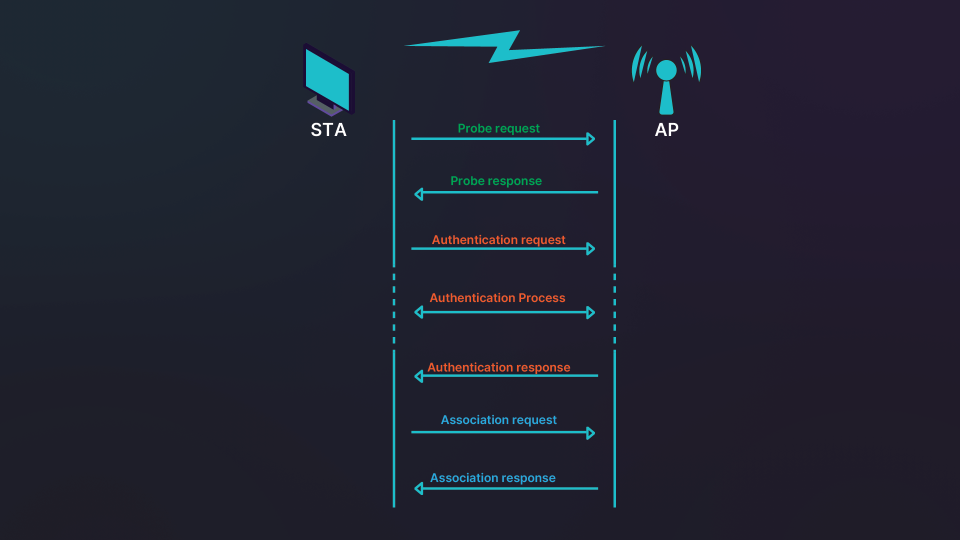
Figure 34: The stages in connecting to a network
We can separate this process into three steps: probe, authentication, and association.
During the probe stage, the client first sends a probe on all channels to find an AP. Then the APs that are in range answer the probe request.
During authentication, the client will usually select the AP with the strongest signal whose SSID was previously chosen in the OS user interface. The actual authentication process varies, depending on, for example, the type of encryption. This stage ends when the AP sends a response to the authentication.
Third is the association stage. The client sends an association request. As with authentication, the length of this part of the process varies. Once this stage has been completed, the client can communicate with the network.
When WPA encryption is used or when on Opportunistic Wireless Encryption (OWE) networks, there is one more step. After association, a client is required to go through key exchange and verification. This is required to be able to to use the network.
Let's explore how these different phases happen on network with different encryption schemes.
5.4.1. Open Network
This section includes a reference file, open.pcap, in the Resources section.
We will now open up our network capture and peer into the workings of wireless networks. We will first review a beacon from the network, the first frame, which gives details about the network. Although beacons occur about 10 times a second, this capture only contains one for brevity since beacons are all identical.
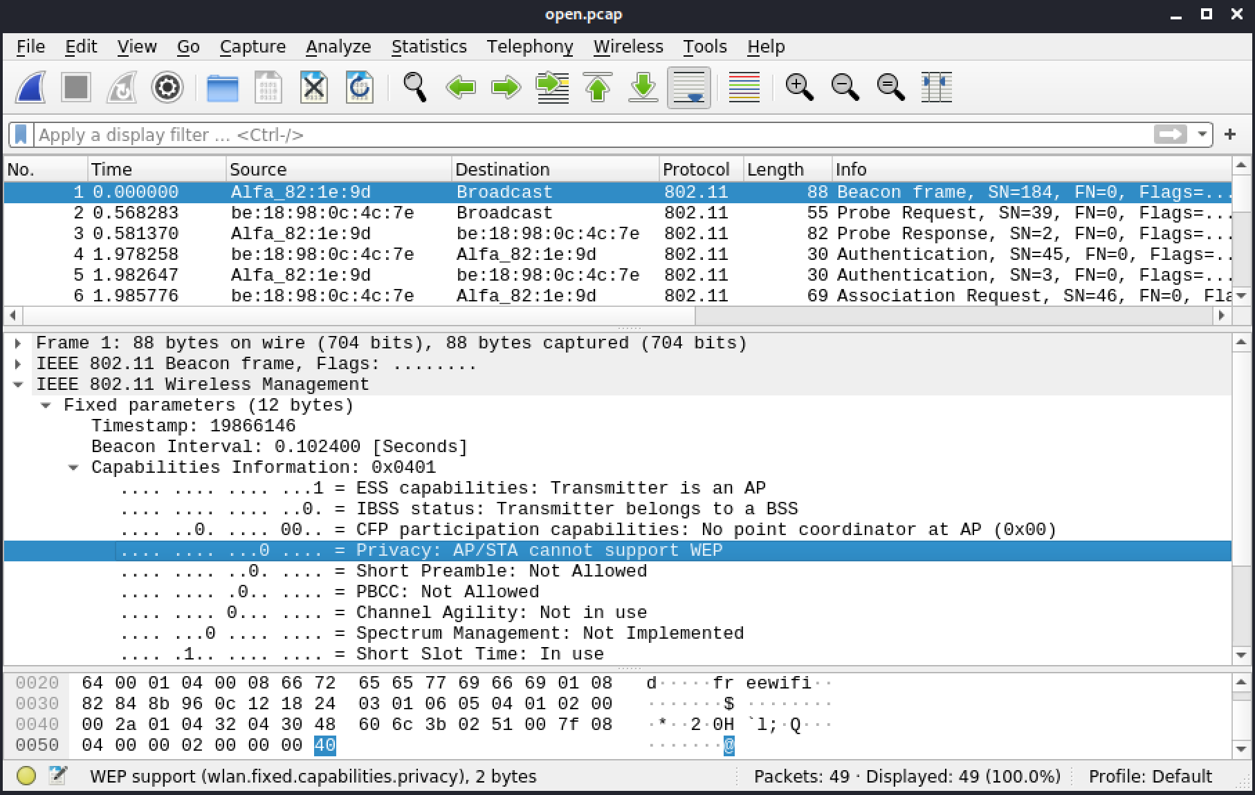
Figure 35: Privacy bit
In IEEE802.11 Wireless Management > Fixed Parameters > Capabilities information, the Privacy bit indicates that the AP is not encrypted.
Tagged parameters includes more details about this network. The first parameter tells us the SSID of the network, "freewifi". The channel, 6, in DS parameter set indicates the AP is operating in the 2.4GHz. The protocol could be 802.11b, 802.11g, 802.11n, or a combination of those. The Supported rates shows 802.11b rates, and Extended supported rates shows 802.11a/g rates.
Since we know the 2.4GHz frequency band supports rates between 1 and 54Mbps, we can conclude that the network is 802.11b/g.
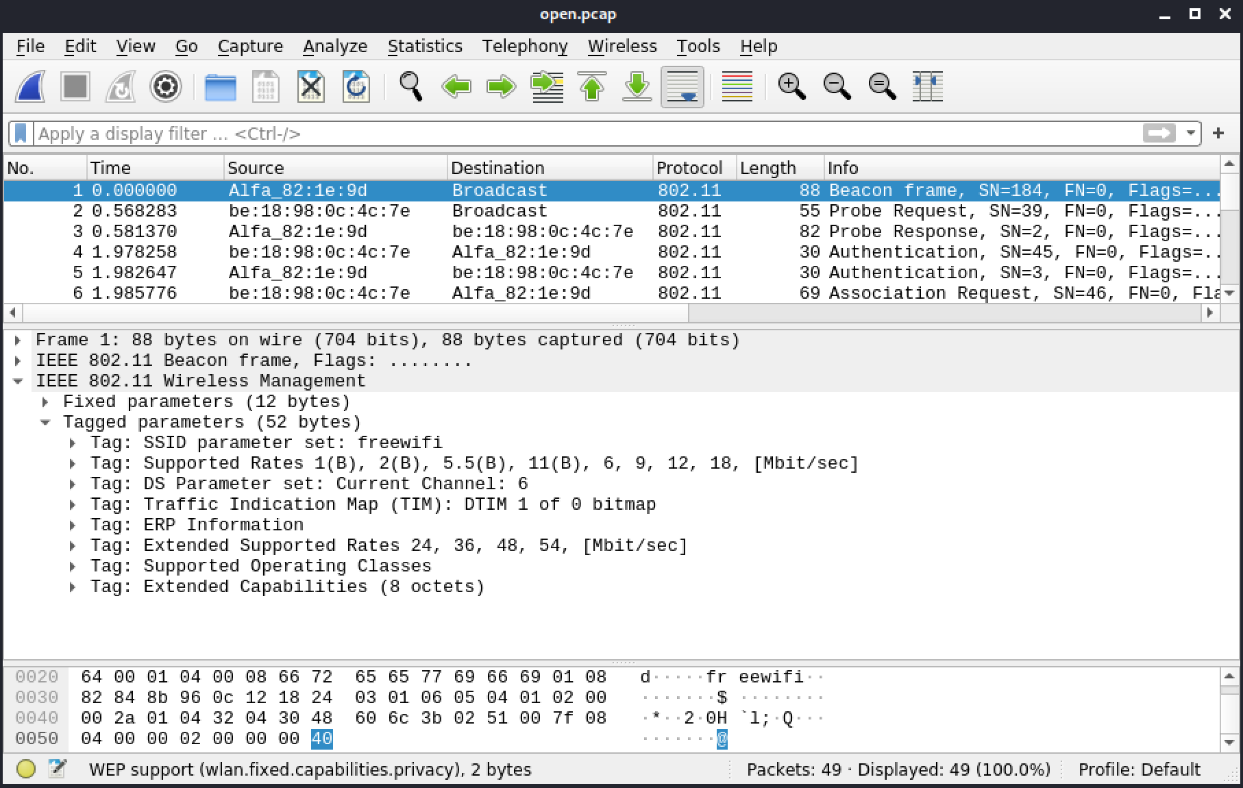
Figure 36: Tagged parameters
The connection process we explained earlier is present here in frames 2 to 7. Frames 2 and 3 are the probe and response. After this, the authentication process takes place in frames 4 and 5. Finally, the association process happens in frames 6 and 7.
In frame 2, the probe request, we may note that Wireshark has marked the SSID parameter as Wildcard. When we open this field, we note that there is no SSID present, which means the client is searching for any AP within range.
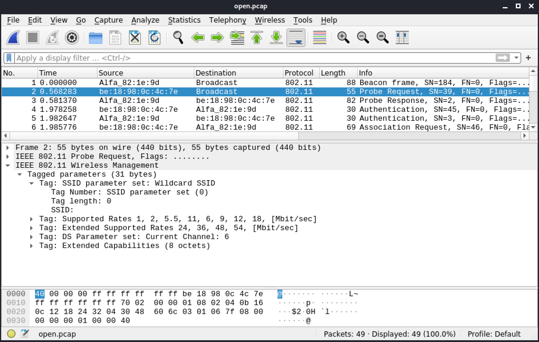
Figure 37: SSID parameter set
Any AP hearing this frame will answer the probe request. The response from freewifi is in frame 3. The information in the IEEE802.11 Wireless Management section is identical to the content of its beacon.
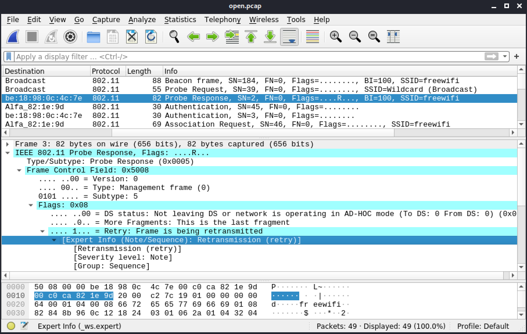
Figure 38: Retry
In the flags in the Info column, the R, which stands for retry, shows that a frame has been resent by the AP. In this case, we might guess that the client was scanning on other channels and didn't receive or acknowledge an answer from the AP. Since the answer wasn't acknowledged, the AP resent it.
After completing the probe process, the client begins authentication with frame 4. In the following figure, the client is trying Open Authentication. Although Shared Authentication is an option for this field, it is not available for open networks.
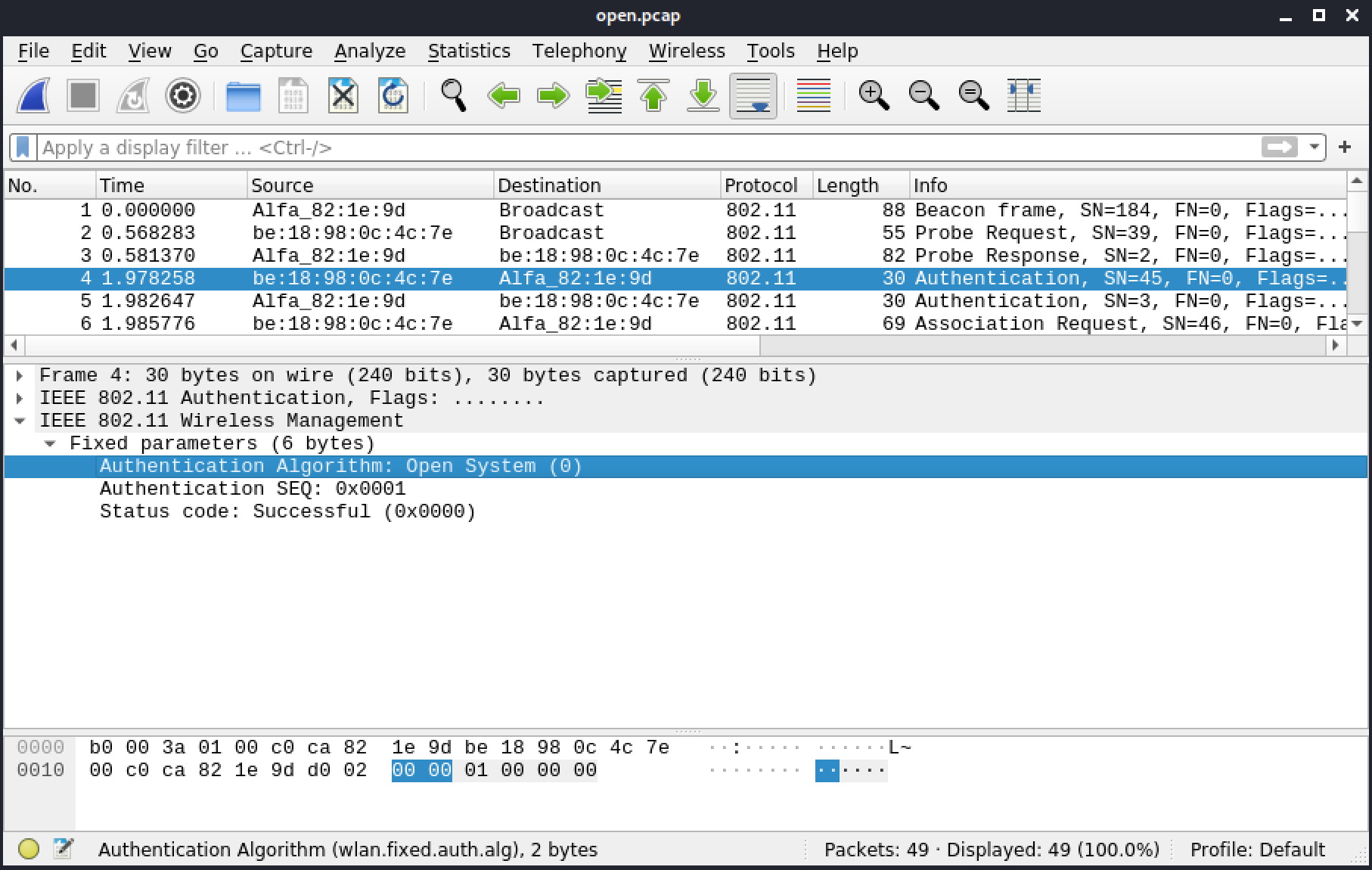
Figure 39: Authentication algorithm
The response from the AP is in frame 5, which indicates the authentication was successful.
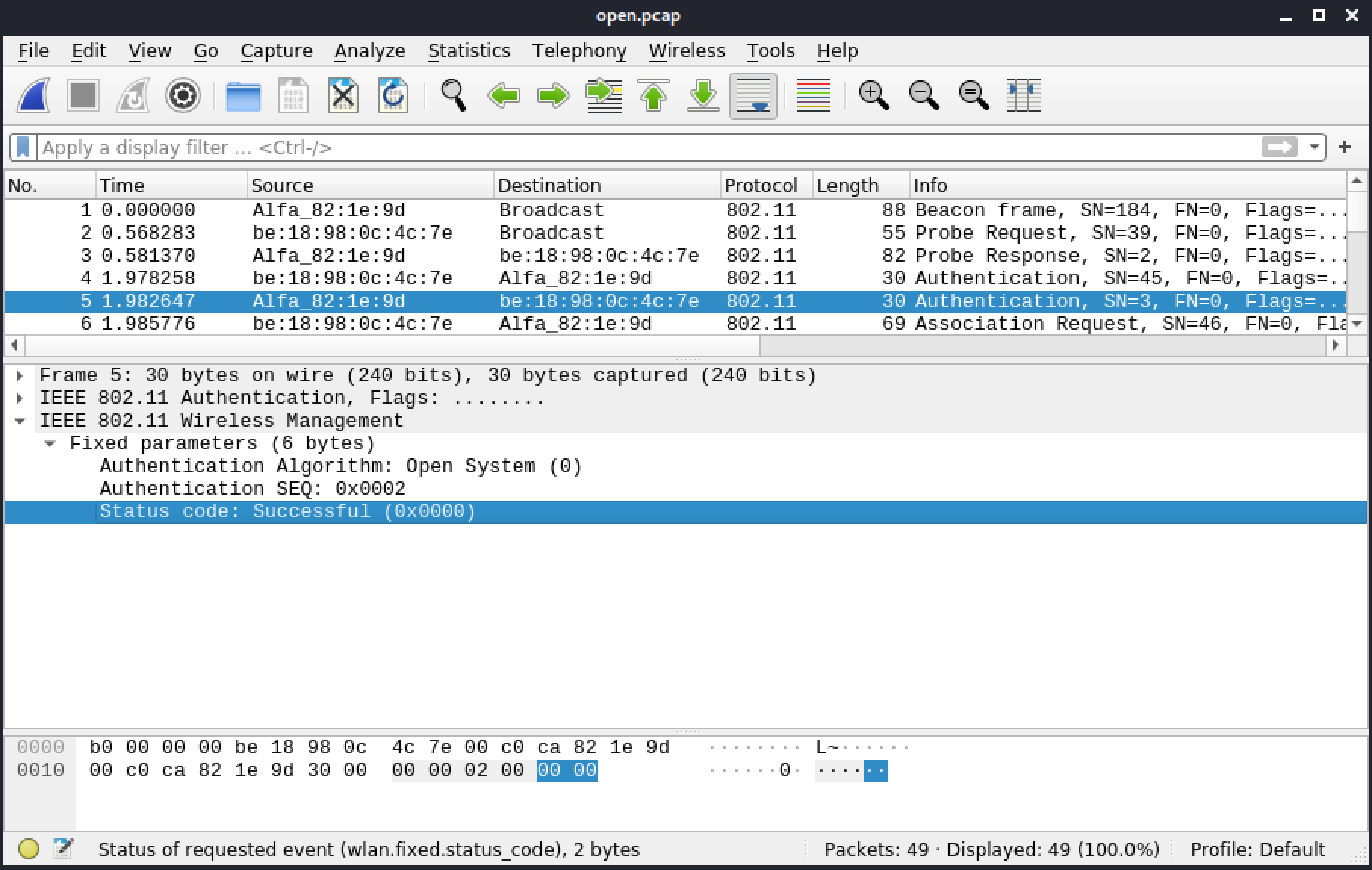
Figure 40: Status code Authentication
Now, in frame 6, the client begins the association process by sending an association request. The client must provide the SSID and the rates or it won't be able to connect.
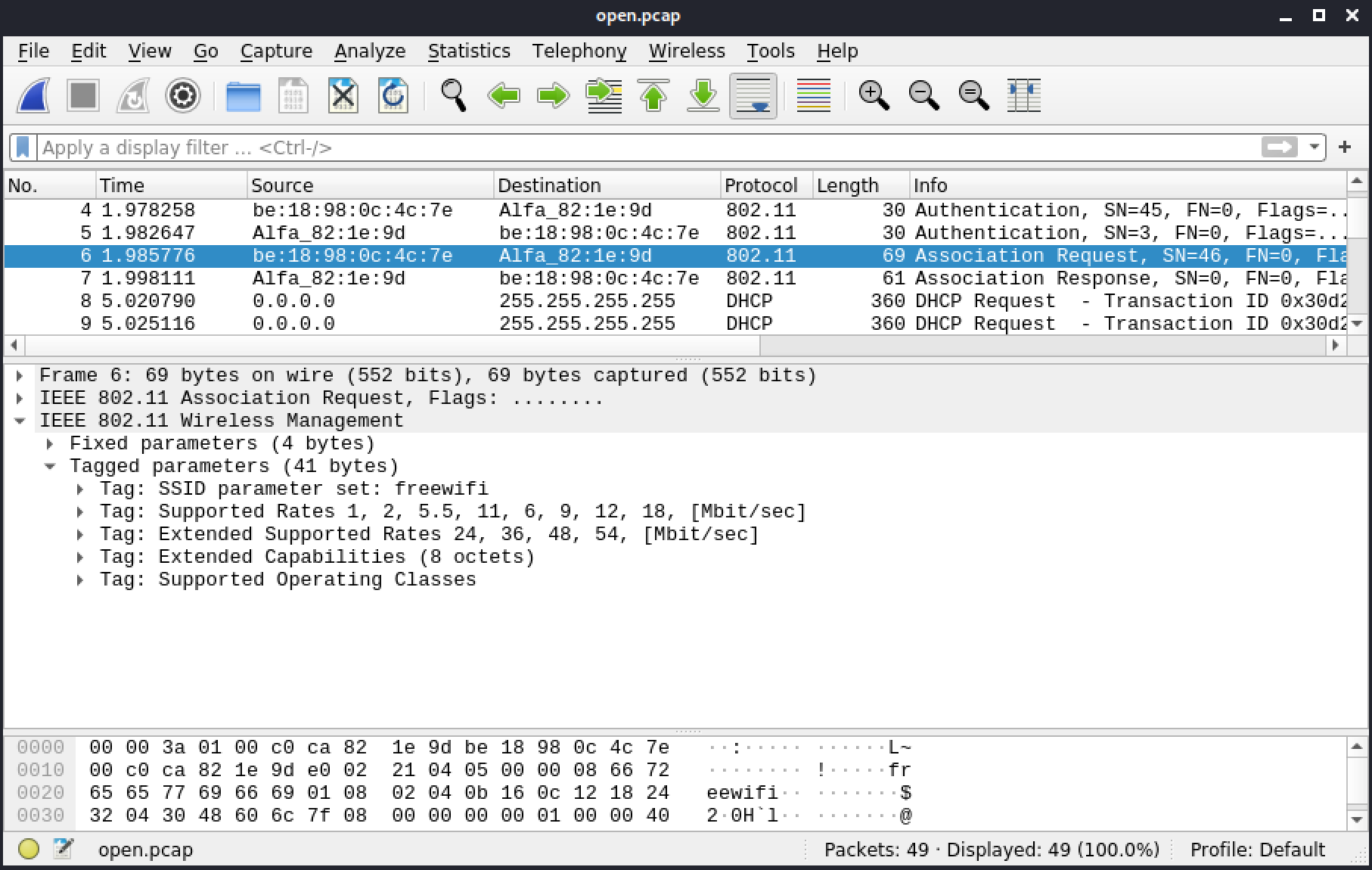
Figure 18: Association request
In frame 7, the AP accepts the association. The highlighted Status code in Figure 41 indicates that the association was successful.
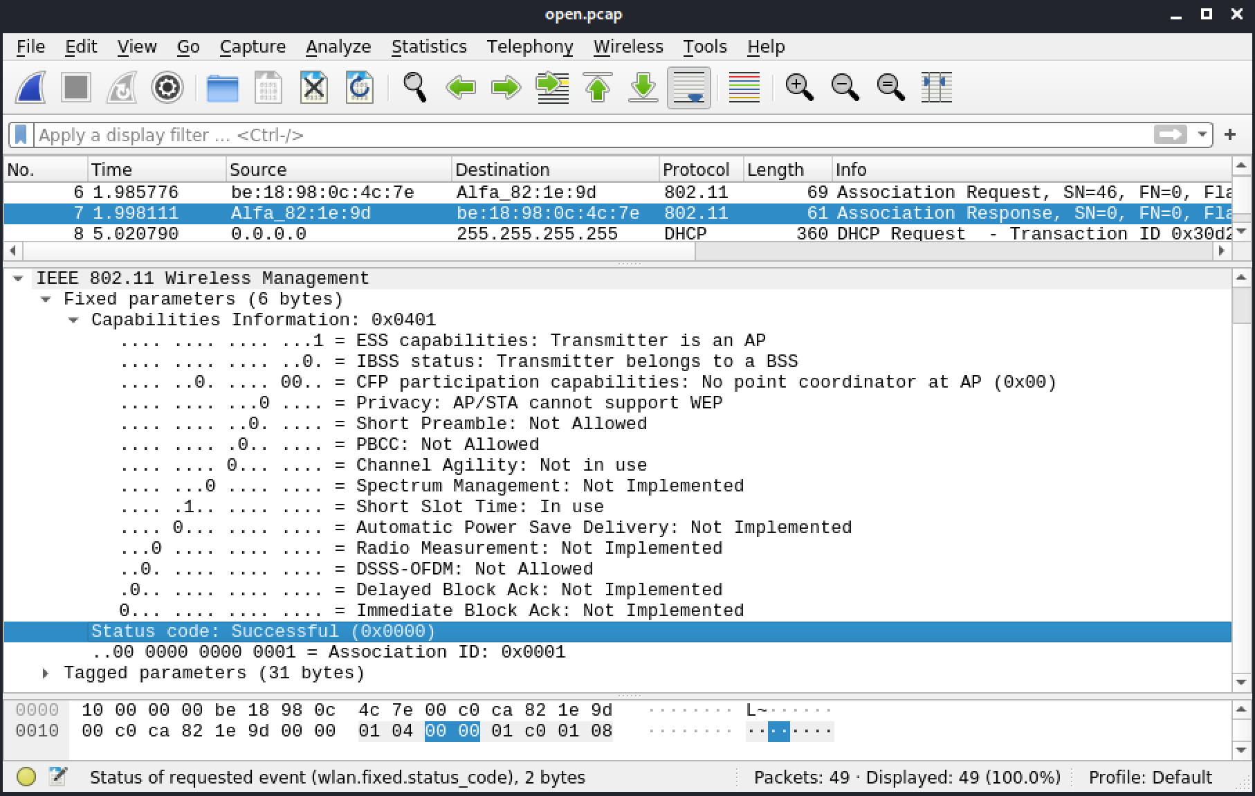
Figure 41: Association Status code
At this point, the client is able to communicate on the network. It sends a DHCP request because it doesn't have an IP address and it needs other network information. There is no encryption on this network, so the DHCP request is visible in frames 8 to 16. The Your (client) IP address field in frame 16 includes the IP address that the client was granted, 192.168.200.137.
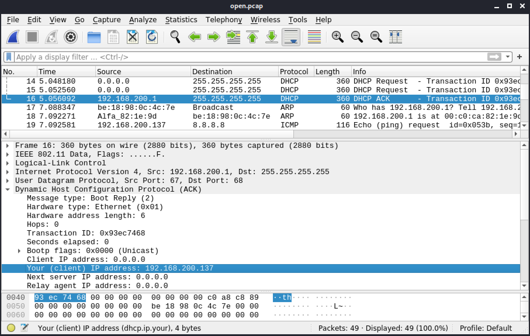
Figure 42: DHCP IP address
In frames 19 to 25, the client is pinging 8.8.8.8.
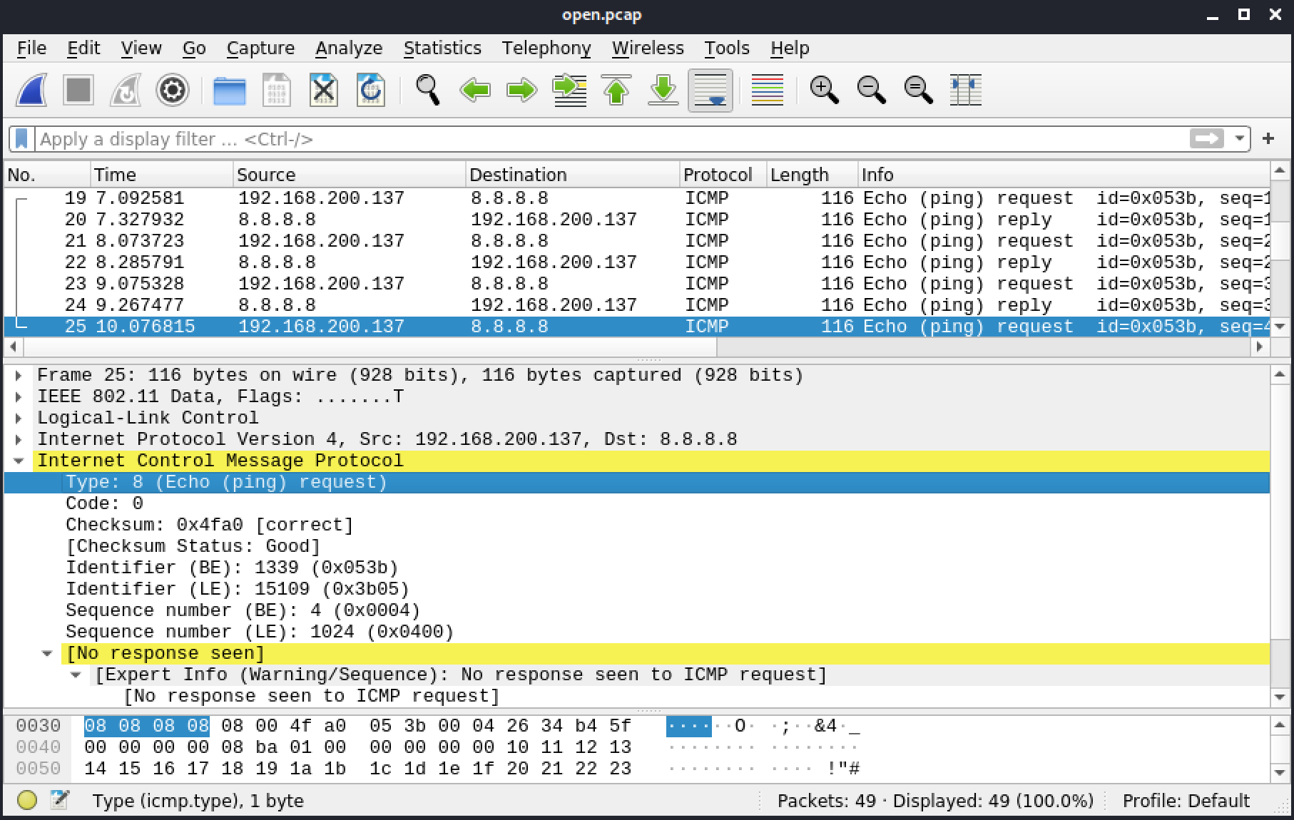
Figure 43: Pinging 8.8.8.8
The last frame doesn't have a response, but that doesn't necessarily mean a response wasn't sent. Sometimes, as a result of our location or interference, we might not necessarily hear or capture every single frame.
In frame 28, a device is trying to resolve example.com. The response, in frame 29 includes an IP address of 93.184.216.34.
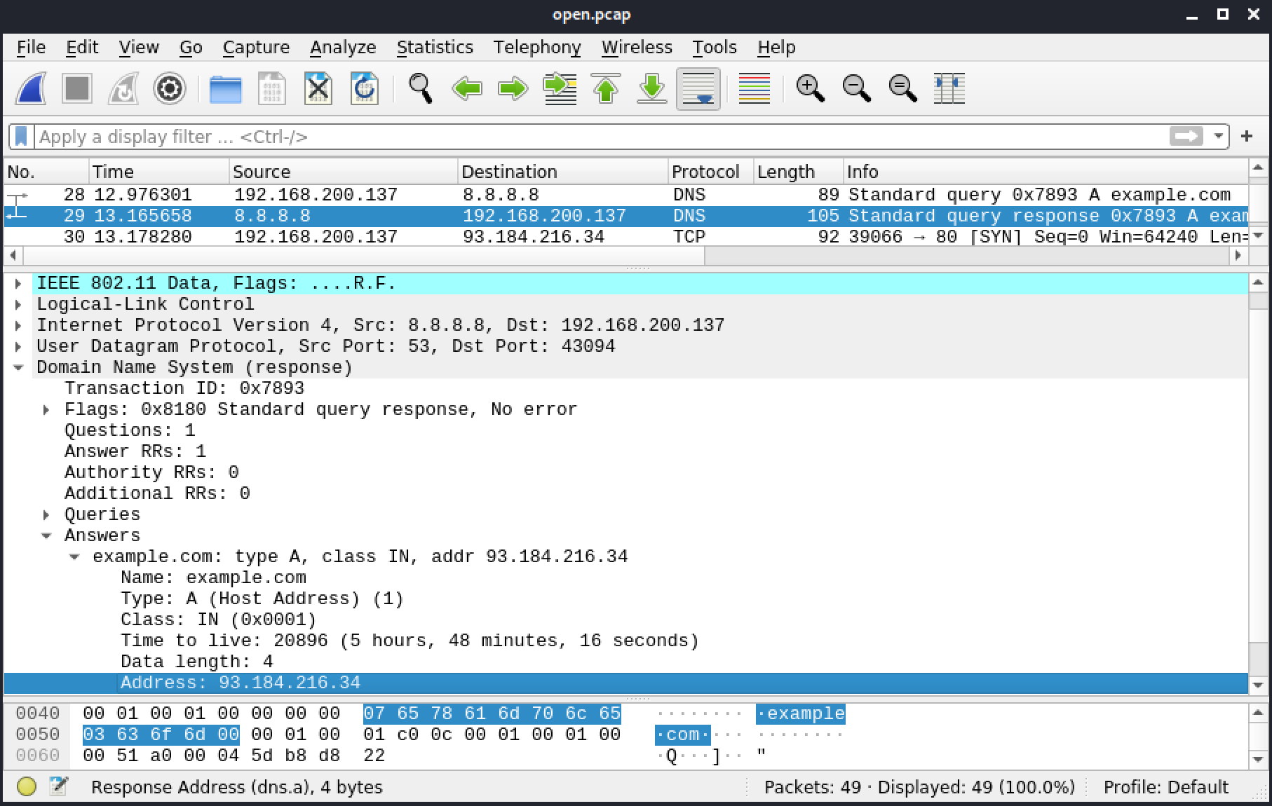
Figure 44: Answers
We can also notice another R in the flags of IEEE802.11 Data, which indicates this frame was retried. The client didn't hear the first time the response was sent.
Frames 30 to 49 are the frames for the website http://example.com. The request is in frame 34:
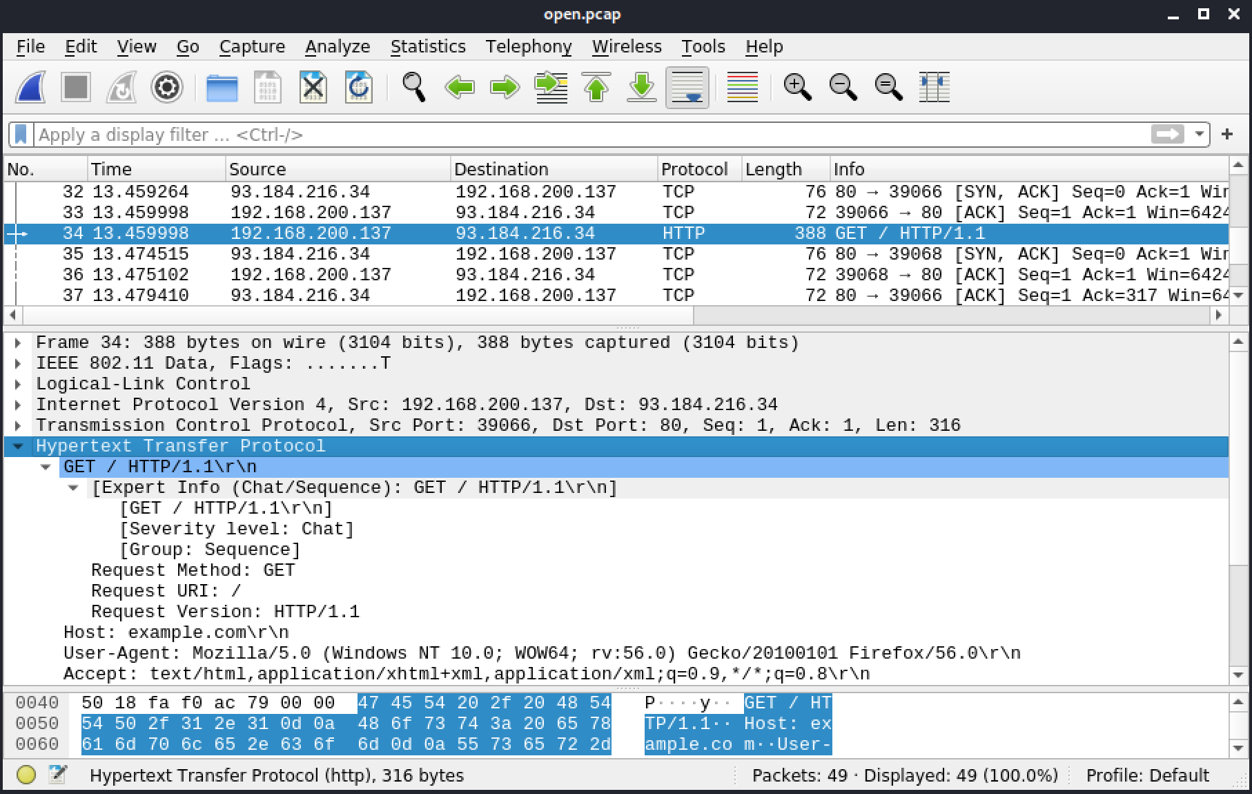
Figure 45: HTTP
Frame 38 includes the response from the server, 200/OK, which means the page exists. This frame also includes the following data.
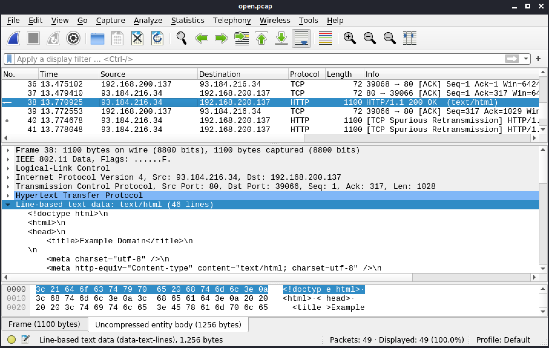
Figure 46: Line-based text data
In frame 42, the browser requests the icon of the websites by querying the favicon.ico. In frame 44, the server returns a 404 because it doesn't have one.
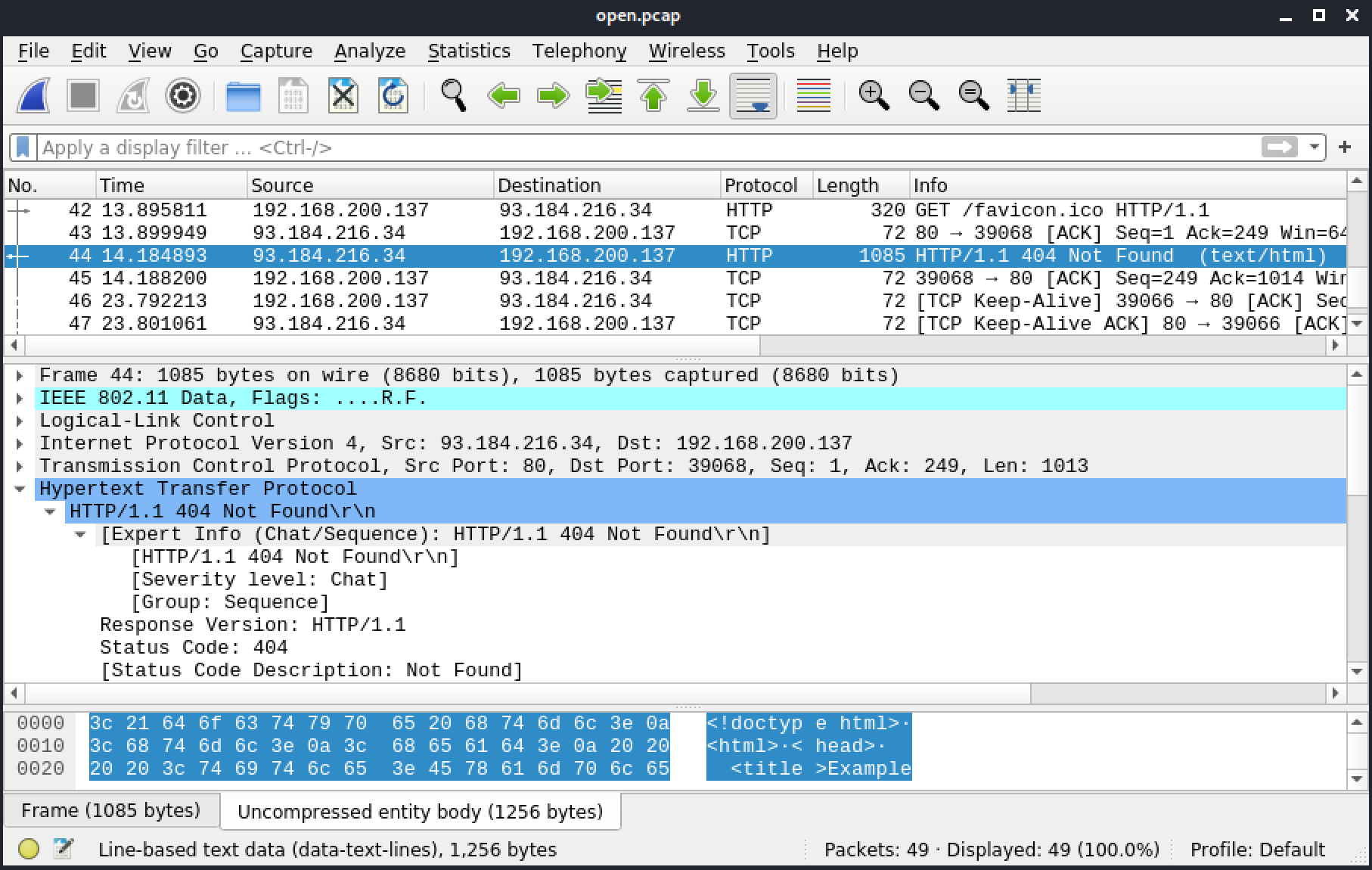
Figure 47: 404 error
5.4.2. EAPoL
Next we'll explore the Extensible Authentication Protocol over LAN (EAPoL) frames, which are commonly used during the handshake when connecting to an AP with WPA, WPA2, WPA3, or OWE. We will also encounter them during a WPS exchange, or when Protected Management Frames, 802.11w, is used on the network.
Before we begin, let's review the EAPoL frame format that will be used in the handshakes we'll review.
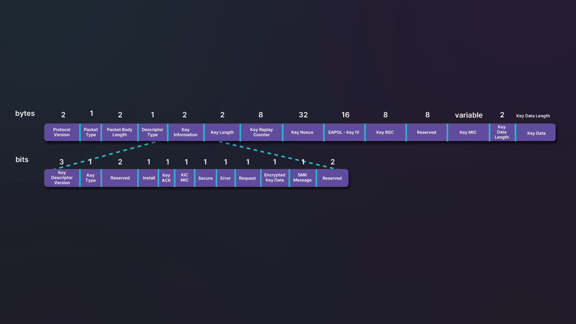
Figure 48: EAPoL-Key frame structure
The authentication section of the EAPoL frame is divided into several fields.
- The Protocol Version (1 byte) has a value of 1, 2, or 3. These values represent 802.1X-2001, 802.1X-2004, or 802.1X-2010 respectively. Values of 1 and 2 are the most common.
- The Packet type (1 byte) usually has a value of 3, which means it is a key.
- The Packet Body Length field (2 bytes) indicates the packet body length or the amount of data after this field.
- The Descriptor Type (1 byte) usually has a value of either 2, which indicates "EAPoL RSN Key" when WPA2 is in use, or 254, which indicates "EAPoL WPA Key" when WPA1 is in use.
- The Key Information (2 bytes) specifies the characteristics of the key, which is divided in smaller parts.
- The Key Length (2 bytes) gives us the length of the PTK. A value of 5 or 13 indicates WEP40 and WEP104, and values of 16 or 32 indicates TKIP, CCMP, GCMP, BIP-CMAC, or BIP-GMAC cipher.
- The Replay Counter (8 bytes) is increased incrementally each time EAPoL frames travel back and forth. This helps to avoid replaying old messages. The Replay Counter is usually 1 in the first part of the handshake (frame 1 and 2) and 2 in the second part. In cases when the exchange fails, because of an incorrect key or a weak signal, the number will go higher.
- The Key Nonce (32 bytes) contains a nonce from the transmitter.
- The EAPoL Key IV (16 bytes) contains the IV used with the KEK. When it's not required, this field will contain a 0.
- The Key Receive Sequence Counter (8 bytes) is used in message 3 and 4, to indicate the counter for the GTK. It is not used with WEP, but does have a few other uses.
- The Key Identifier (8 bytes) is an unused field, reserved for future use. It is set to 0.
- The Key MIC field (variable size) is the MIC of this packet, called EAPoL-Key, from and including Protocol Version. Its size will depend on the AKM used.
- The Key data length field (2 bytes) defines the length of the upcoming Key Data field.
- The Key Data field includes additional data for the key exchange. The data may also be one or more Robust Security Network Elements (RSNE) or Key Data Elements (KDE). An RSNE starts with 0x30 and KDE starts with 0xdd.
The Key Information is further divided into a number of smaller fields.
- By default, the Key descriptor version (bits 0, 1 and 2) is set to 0, but could also be set to values of 1, 2, or 3 to indicate a specific algorithm. The values of 1, 2, and 3 are mappings to algorithms used for the MIC, its length, and the encryption key. One (1) is for ARC4 encryption with HMAC-MD5, two (2) is for NIST AES key wrap with HMAC-SHA1-128, and three (3) is NIST AES key wrap with AES-128-CMAC.
- When the Key Type (bit 3) is set, the result is going to be a PTK. When not set, the result is going to be a group key or SMK.
- Bits 4 and 5 are reserved and not in use at this time.
- If Install (bit 6) is set, the client will need to install the keys.
- Key ACK (bit 7) indicates whether or not the receiving party expects an EAPoL-Key message.
- When Key MIC (bit 8) is set, a MIC is present.
- Secure (bit 9) is set when the initial key exchange is complete. It will be set in message 3 (from the Authenticator to Supplicant) and in message 4 (from the Supplicant to Authenticator).
- Error (bit 10) is set when a MIC failure happens.
- Request (bit 11) is only set by a Supplicant in a MIC Failure report. It can also requests the Authenticator to initiate a 4-way handshake or group key handshake.
- The Encrypted Key Data (bit 12) is set if the Key Data field is encrypted.
- SMK Message (bit 13) specifies if the packet is part of a SMK handshake.
Key Data can contain two types of data: key data cryptographic encapsulation(s) (KDE) or RSNE. The structure of KDE is as follows.
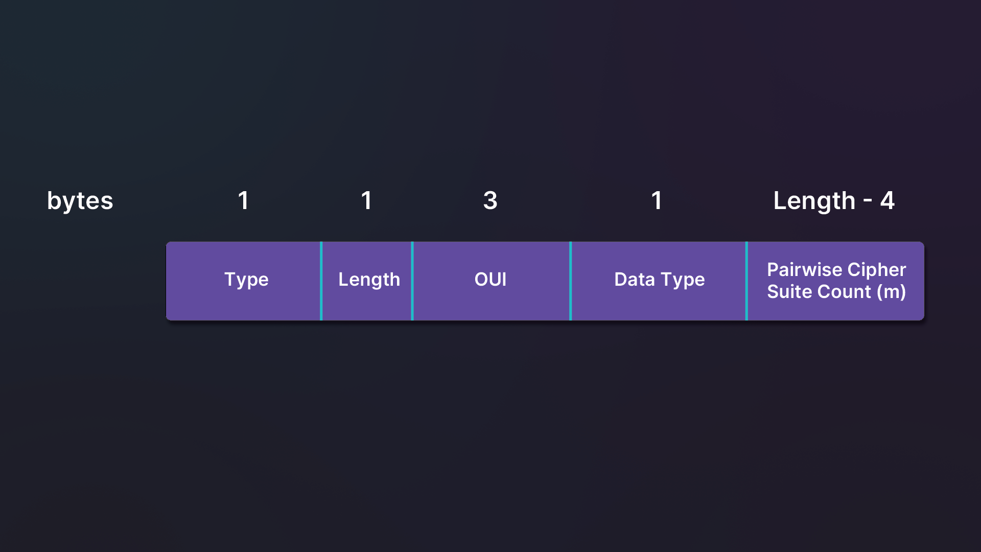
Figure 49: KDE structure
The RSNE structure is a bit more complex.
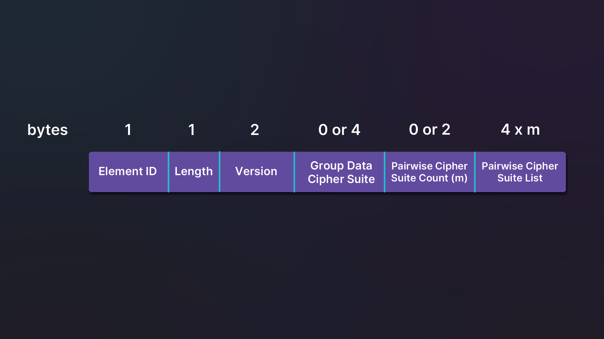
Figure 50: RSNE structure
The last element will only be present if the one before it is also present. The Pairwise Cipher Suite List contains items in the following format.
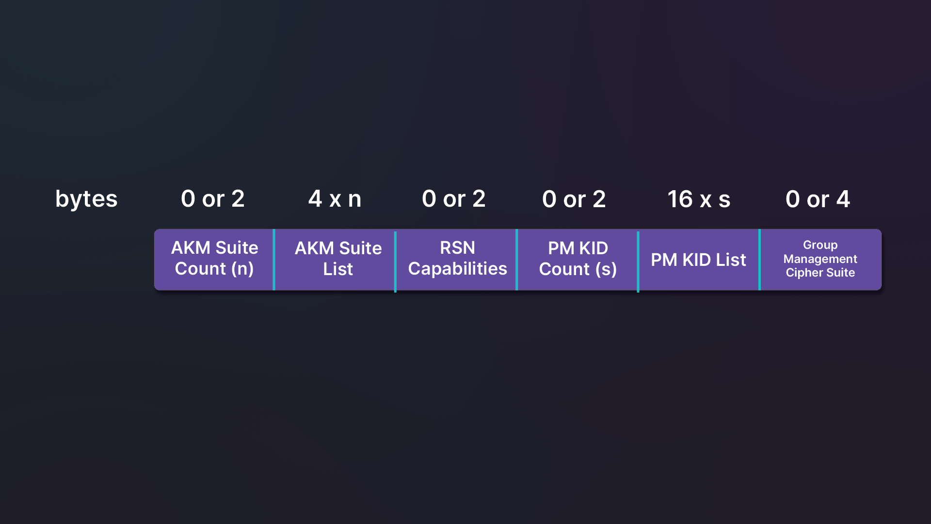
Figure 51: RSNE Pairwise Cipher Suite item
5.4.3. WEP
This section includes 2 reference files:
- WEP Open Authentication
- WEP Shared Authentication
Both in the Resource section.
The connection process for WEP is similar to the one we just explored for open networks. The client will send probe requests and receive responses. Then it will start the authentication process and the association before finally being able to communicate on the network.
The main difference that we will note in the frames, is that the Privacy bit is set in the beacons, probe response, and association frames. The Privacy bit indicates encryption. Because of a lack of WPA or WPA2 tags in these frames, we also know that the security algorithm is WEP.
WEP can be either open authentication or shared authentication. With open authentication, the process is identical to an open network. With shared authentication, the client receives random data called challenge text from the AP. The client has to encrypt the challenge text to prove it has the right key. The AP will then try to decrypt using its own key. If successful, the client will be allowed to continue with association. Shared authentication is much less common than open authentication, and the broadcasting AP doesn't advertise it. For this reason, many clients will try open authentication first. If they get denied one or more times, they will try shared authentication.
5.4.4. WPA1
This section includes a reference file, wpa1.pcap, in the Resources section.
We will be using a display filter, !(wlan.fc.type == 1), in Wireshark to skip over control frames that aren't relevant in this exchange.
The first frame is a beacon from the AP. It advertises WPA1 PSK TKIP.
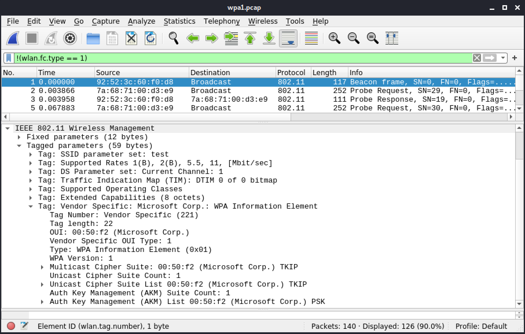
Figure 52: Frame 1: Beacon with WPA IE
The following frame is a probe request, followed by a probe response by the AP. Both have the same IEs.
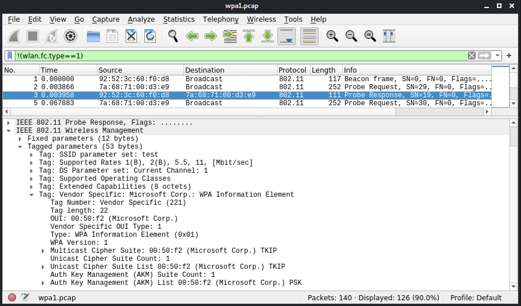
Figure 53: Frame 3: Probe Response with WPA IE
The authentication is similar to one we reviewed earlier. Let's skip to the association request from the client. This request includes an agreement to connect using WPA1 PSK TKIP.
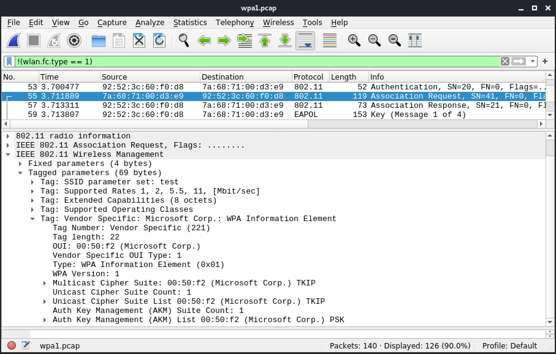
Figure 54: Frame 55: Association request with WPA IE
The association response indicates it is successful.
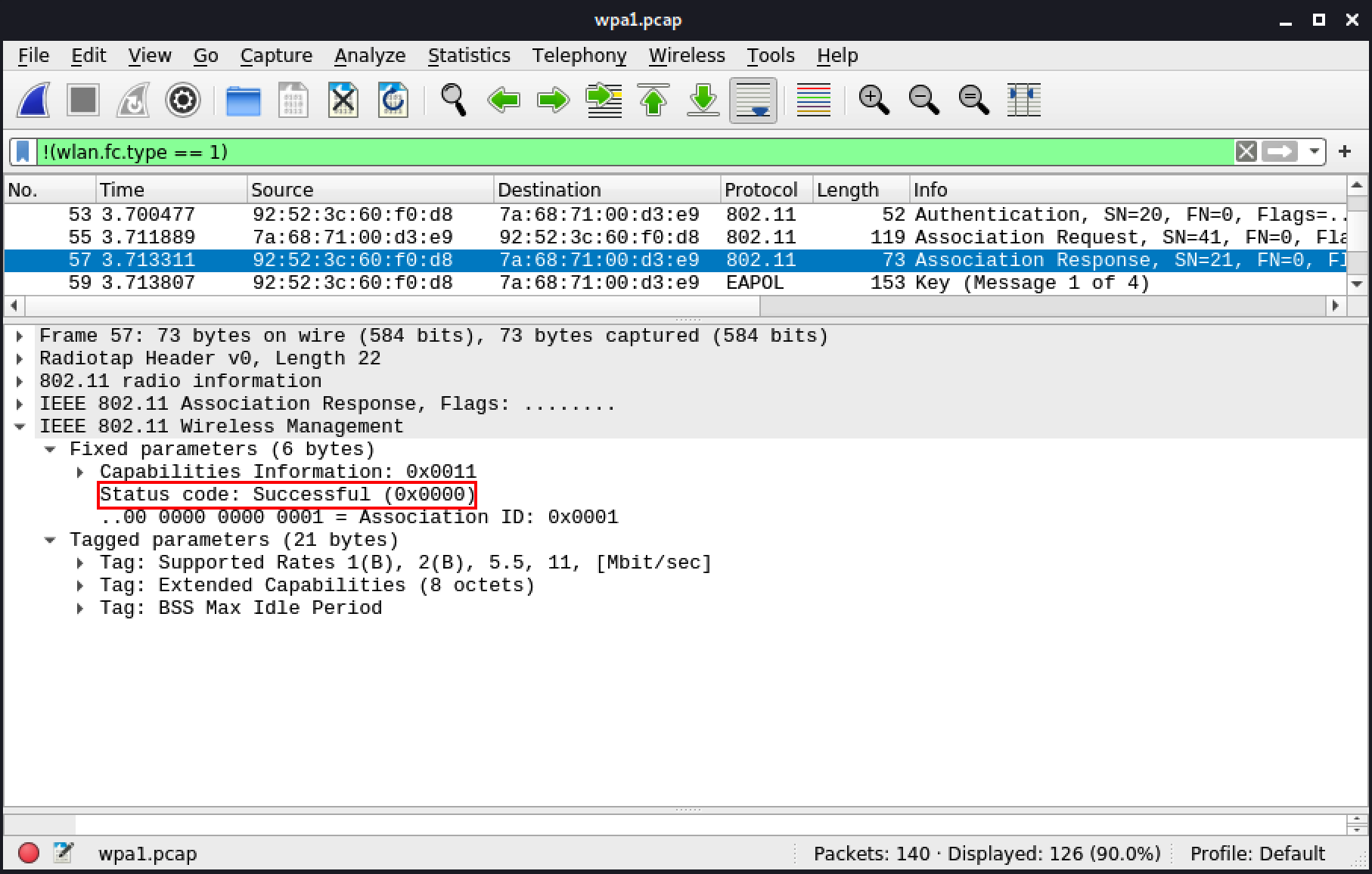
Figure 55: Frame 57: Association response
Afterward, we note the 4-way handshake, which is initiated by the AP.
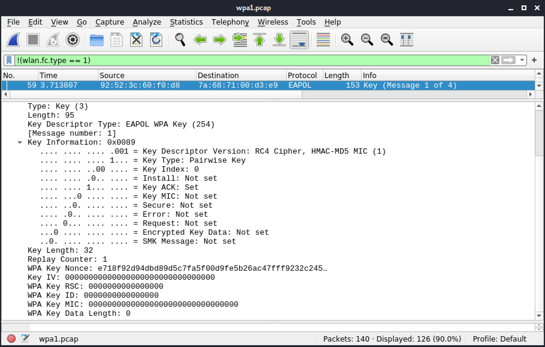
Figure 56: Frame 59: EAPoL message 1
At this point the client generates its nonce. Since it has all the necessary information, it can derive the PTK next.
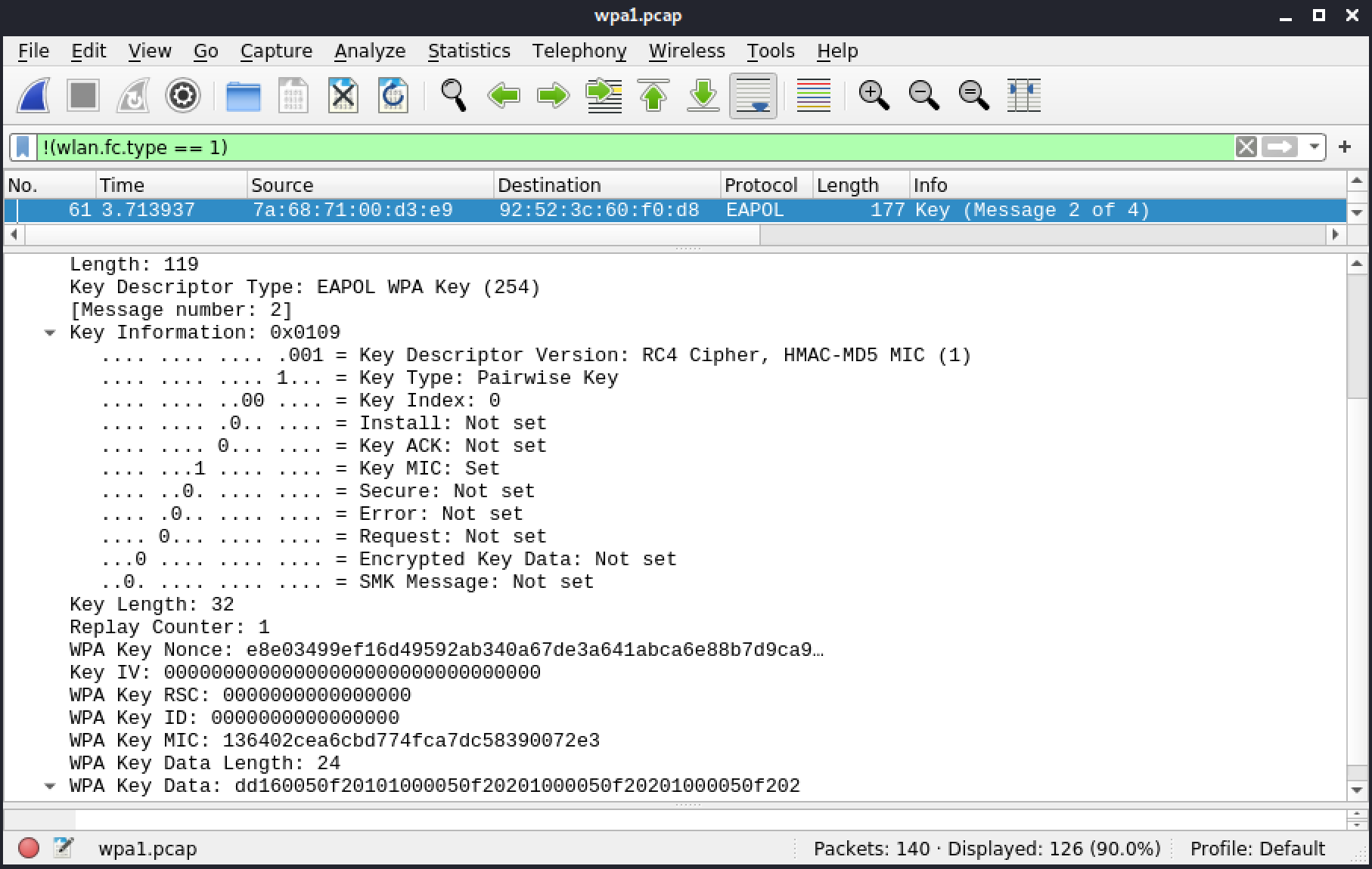
Figure 57: Frame 61: EAPoL message 2 - part 1
Now that the AP, which is the Authenticator in this case, has received the nonce from the client (Supplicant), it can generate the PTK. It will also confirm both supplicant and authenticator share the same key by verifying the MIC. Finally, it will prepare the third message, which contains the GTK.
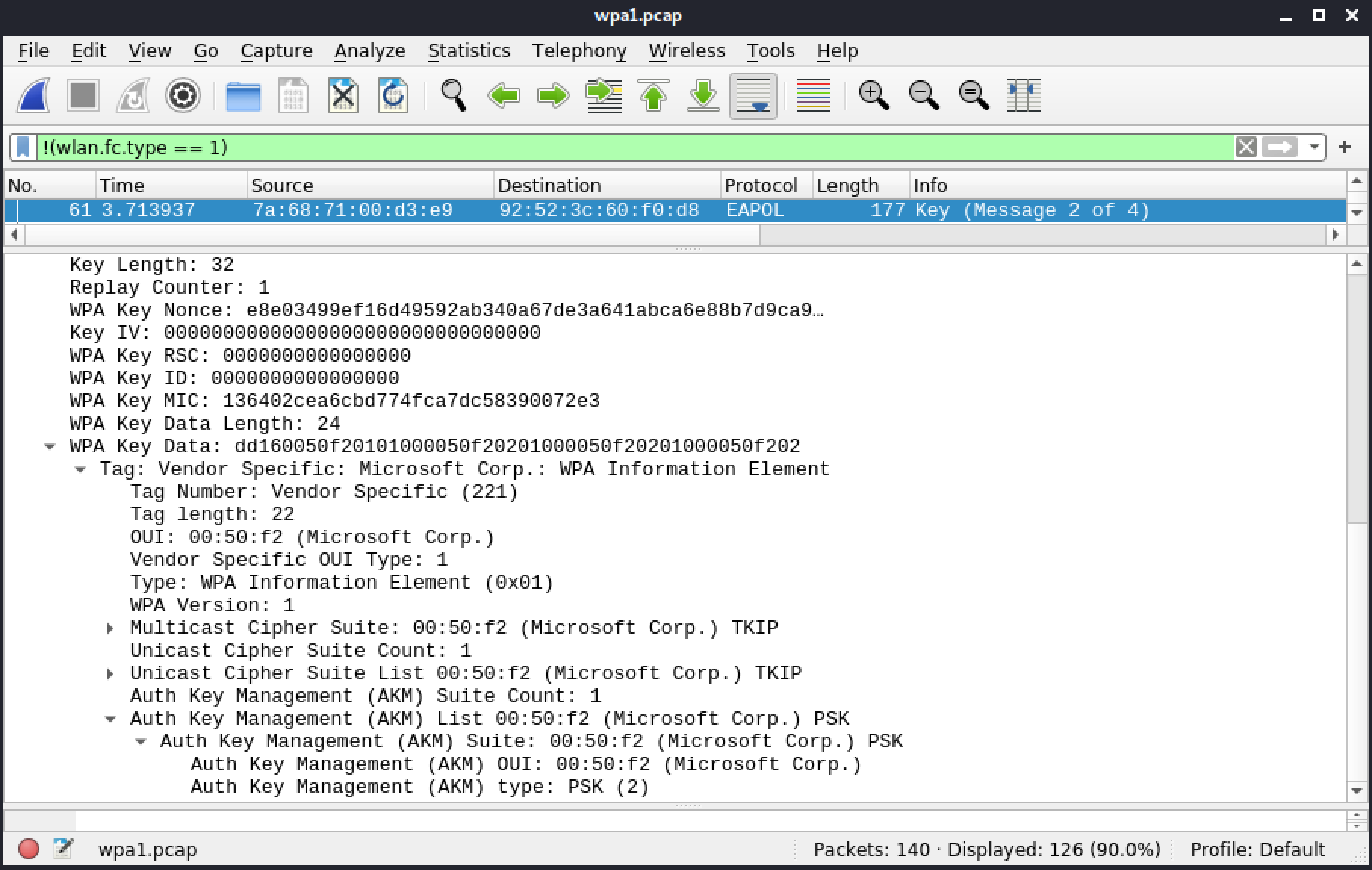
Figure 57: Frame 61: EAPoL message 2 - part 2
In the flags under the Key Information section of this message, the AP tells the client to install the keys.
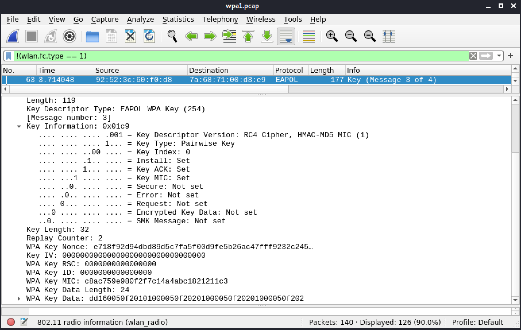
Figure 58: Frame 63: EAPoL message 3 - part 1
The Key Data in this third message contains a KDE within an IE (which are typically found in management frames such as beacons) for WPA1.
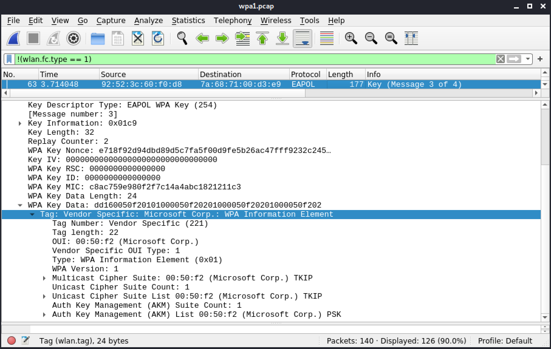
Figure 59: Frame 63: EAPoL message 3 - part 2
The last message is simply an acknowledgment that will allow the flow of encrypted data. The AP will check the MIC and then install the keys for the newly connected client.
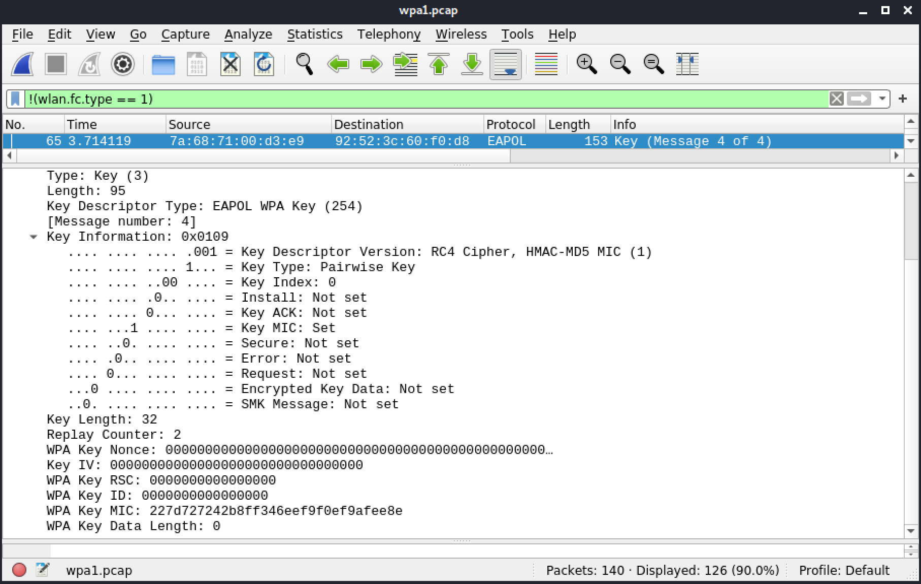
Figure 60: Frame 65: EAPoL message 4
The group key handshake is done afterward, in frames 67 and 69. We will need to decrypt the capture in order to be able to review them.
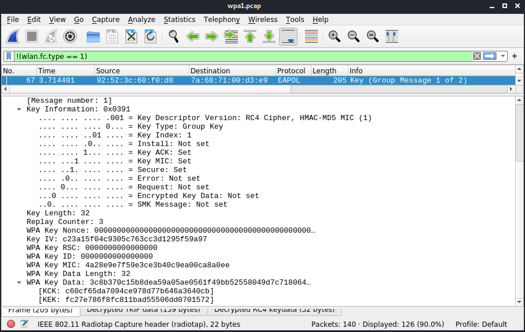
Figure 61: Frame 67: Group Handshake message 1
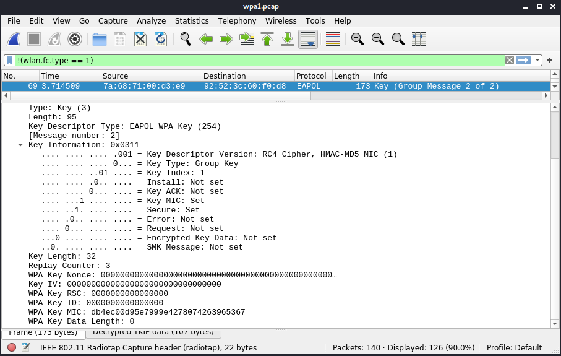
Figure 62: Frame 69: Group Handshake message 2
5.4.5. WPA2
This section includes a reference file, wpa-Induction.pcap, in the Resources section.
The first frame is a beacon from the AP. It advertises WPA1 and WPA2, both with AES/CCMP and TKIP. Group Cipher in both cases is TKIP, which means that all frames that are broadcast or multicast will be encrypted using TKIP. The unicast ones will depend on the cipher selected by the client.
We will be using a display filter, !(wlan.fc.type == 1), in Wireshark to skip over control frames that aren't relevant in this exchange.
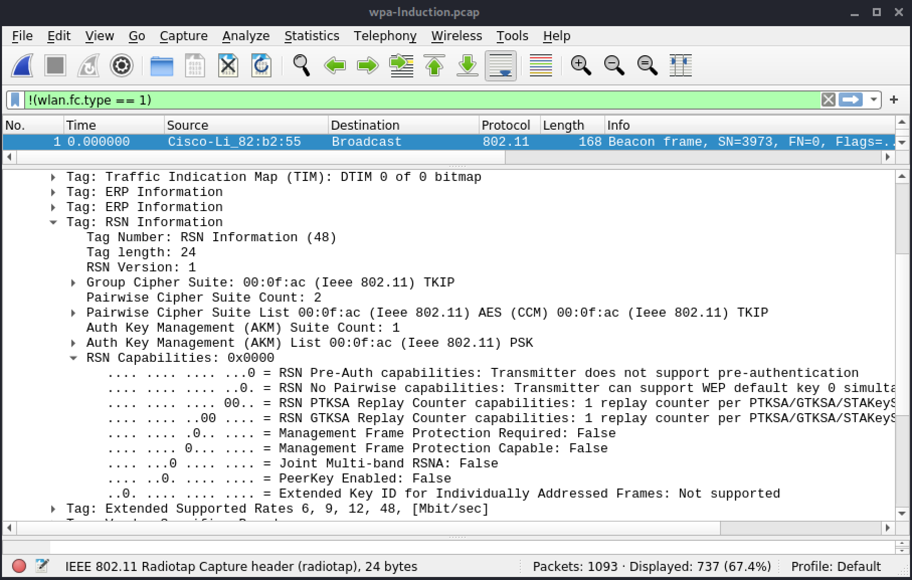
Figure 63: Frame 1: Beacon with RSN IE
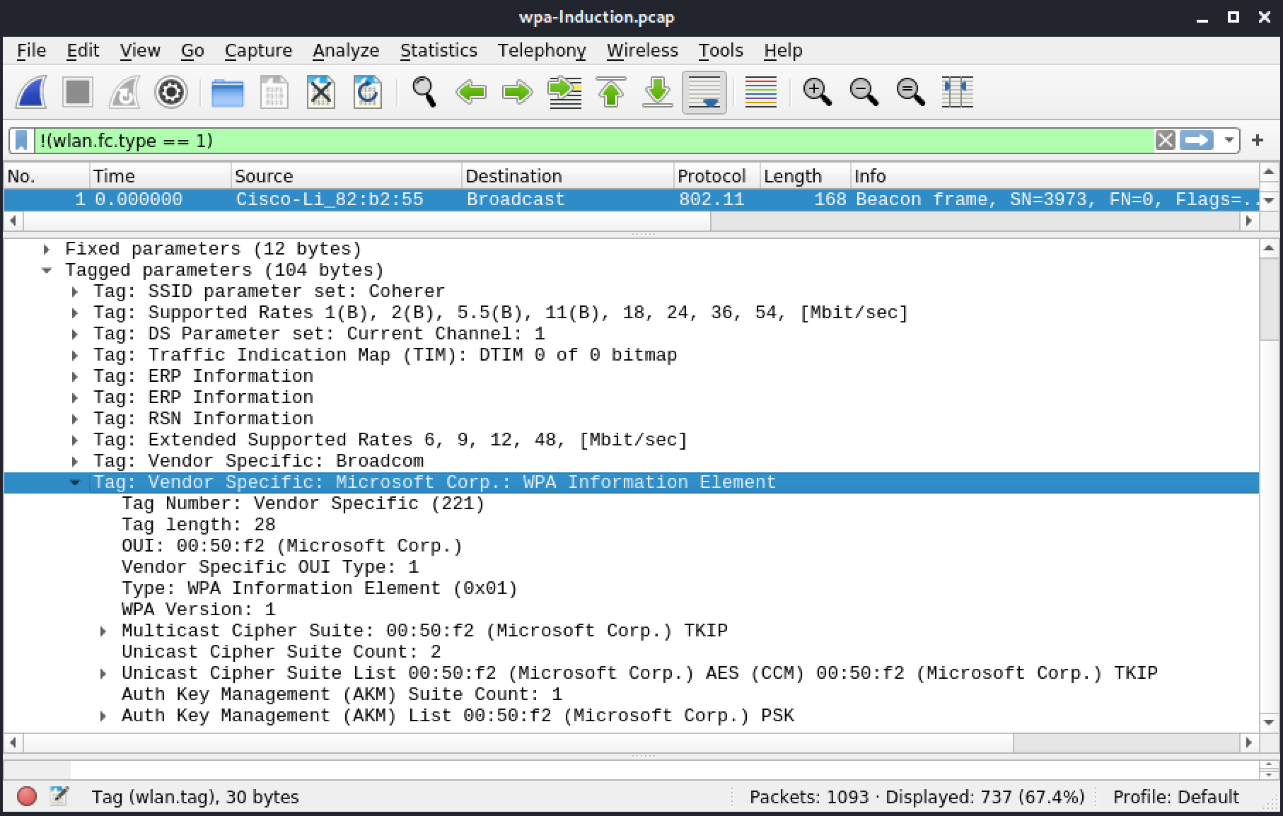
Figure 64: Frame 1: Beacon with WPA IE
The authentication section is uneventful (frames 78 and 80). In the association request (frame 82), the client is selecting WPA2 with AES or RSN as well as TKIP for the group cipher.
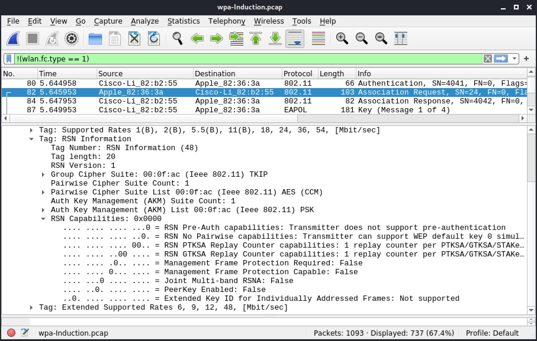
Figure 65: Frame 82: Association request with RSN
The AP responds with a successful Association Response (frame 84), and then proceeds to start the 4-way handshake.
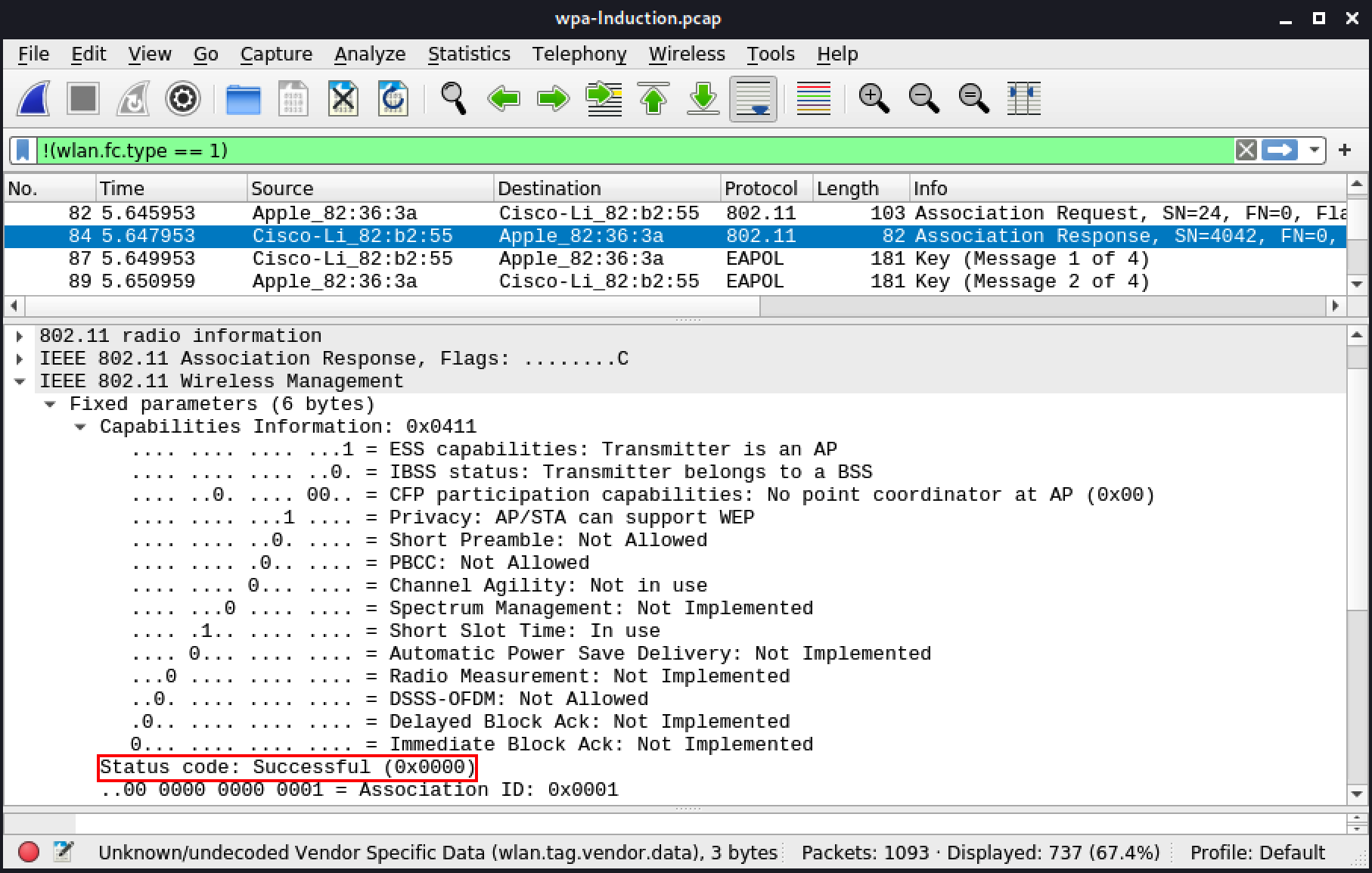
Figure 66: Frame 84: Association response
This 4-way handshake is similar to the one in the WPA1 section. There are a few key differences because it is WPA2 CCMP.
In this first EAPoL message, the key information indicates it's using CCMP with HMAC-SHA1 MIC.
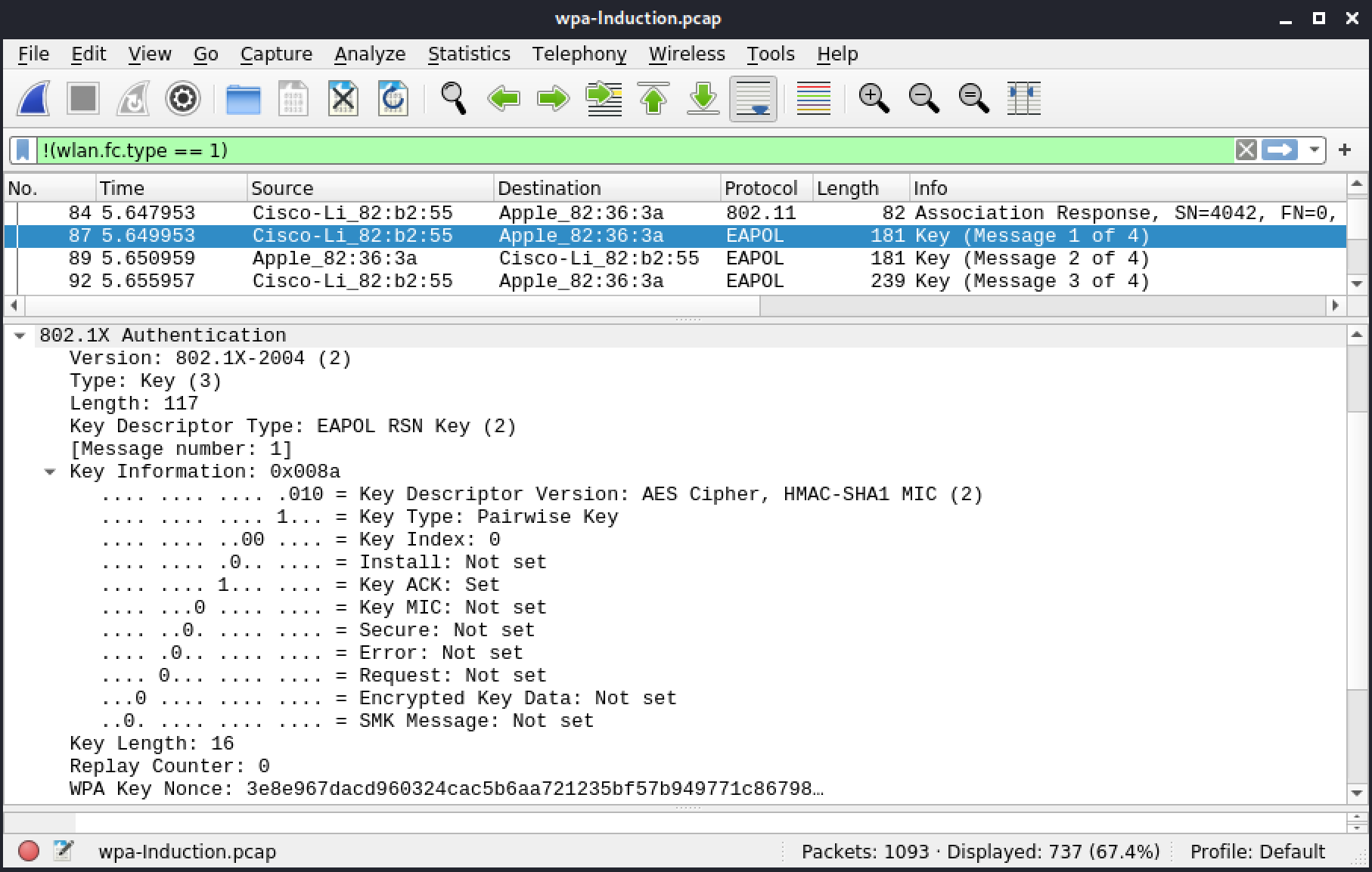
Figure 67: Frame 87: 4-way handshake (EAPoL message 1) - part 1
The WPA Data field shows an RSNE with a PMKID.
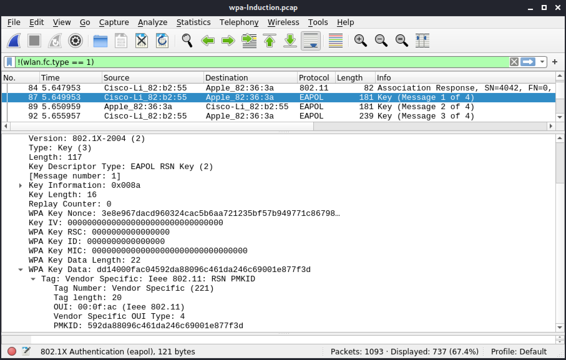
Figure 68: Frame 87: 4-way handshake (EAPoL message 1) - part 2
We note an RSNE in the WPA Key Data field, showing details of the cipher used.
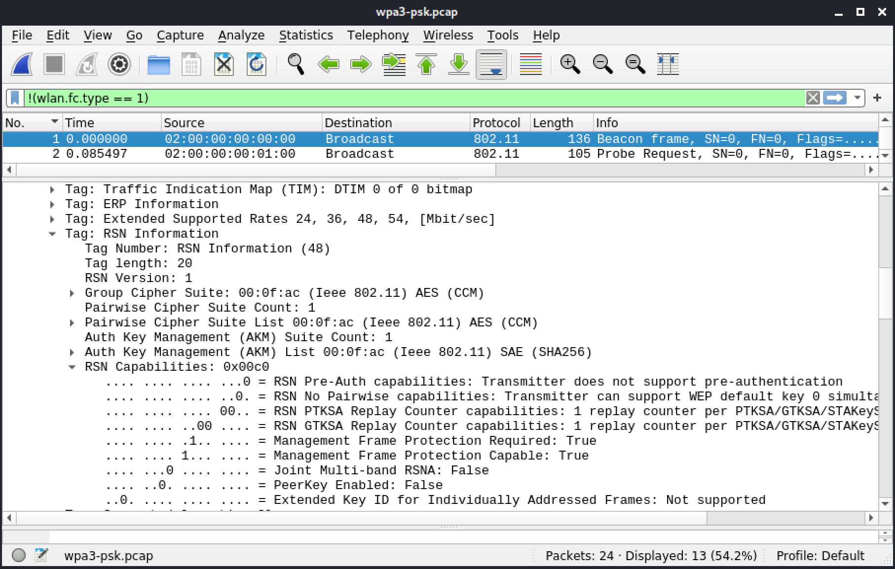
Figure 69: Frame 1: Beacon
The second frame is a probe request and the third is a response to that request. It contains the same IEs as the beacon and advertises SAE, 802.11w, and BIP in the RSN IE. There is one exception, the Traffic Indication Map.
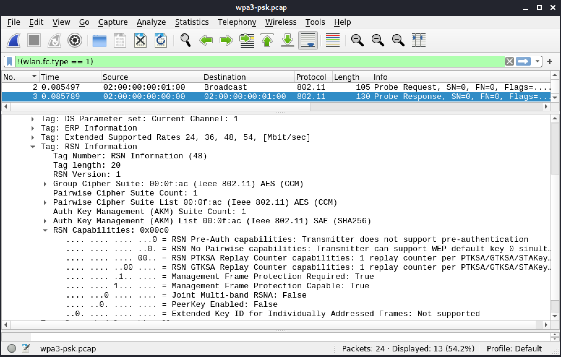
Figure 70: Frame 3: Probe response
The dragonfly handshake occurs during authentication part. In the first authentication frame (5), we note that the algorithm isn't "Open authentication" like it was with WEP, WPA1, or WPA2. Now the algorithm is Simultaneous Authentication of Equals (SAE) using the default group, 19. This first authentication frame is the start of the commit phase where both sides commit to a shared secret.
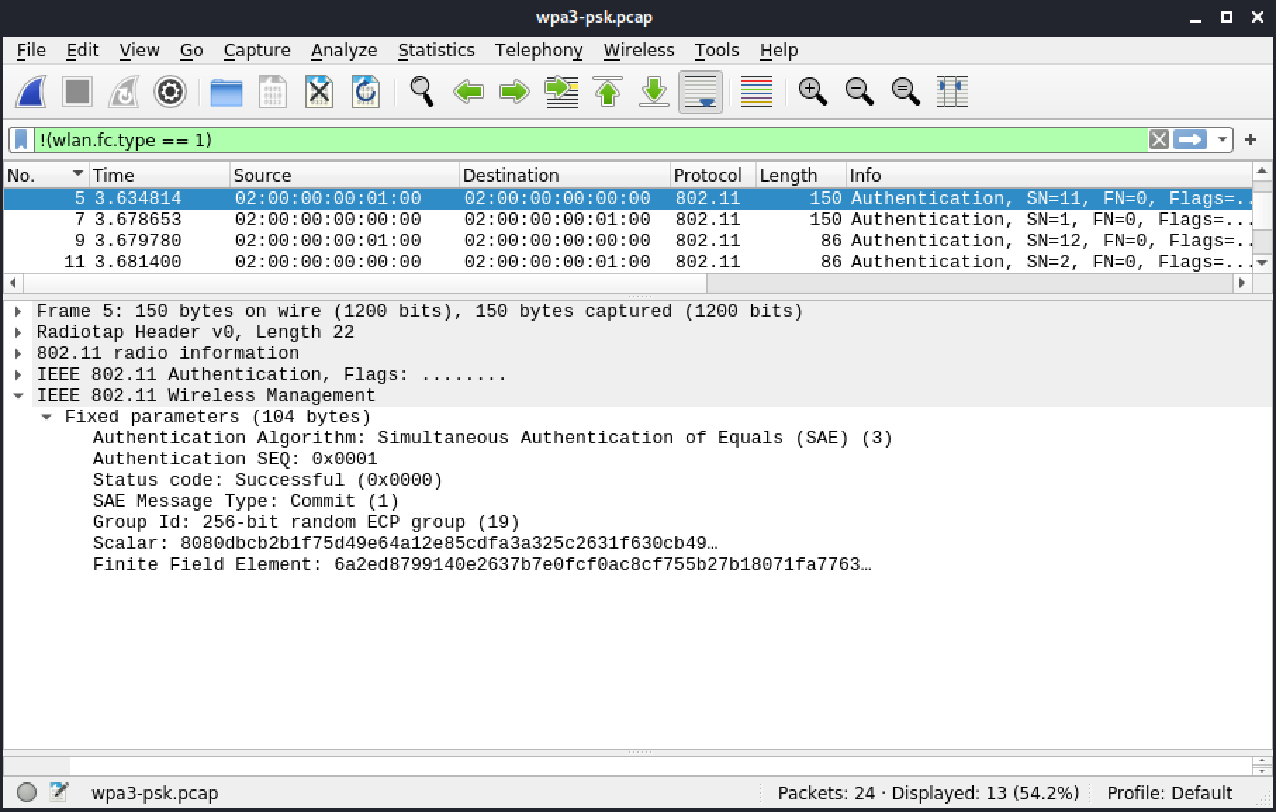
Figure 71: Frame 5: Authentication - Commit message from client
The second frame (7) of the authentication stage is where the AP sends its scalar and finite field element.
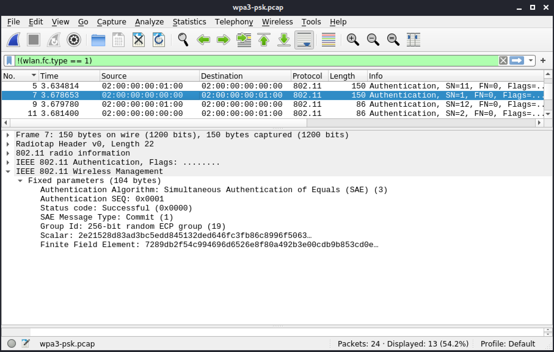
Figure 72: Frame 7: Authentication - Commit message from AP
This next frame (9) is the confirm message from the client.
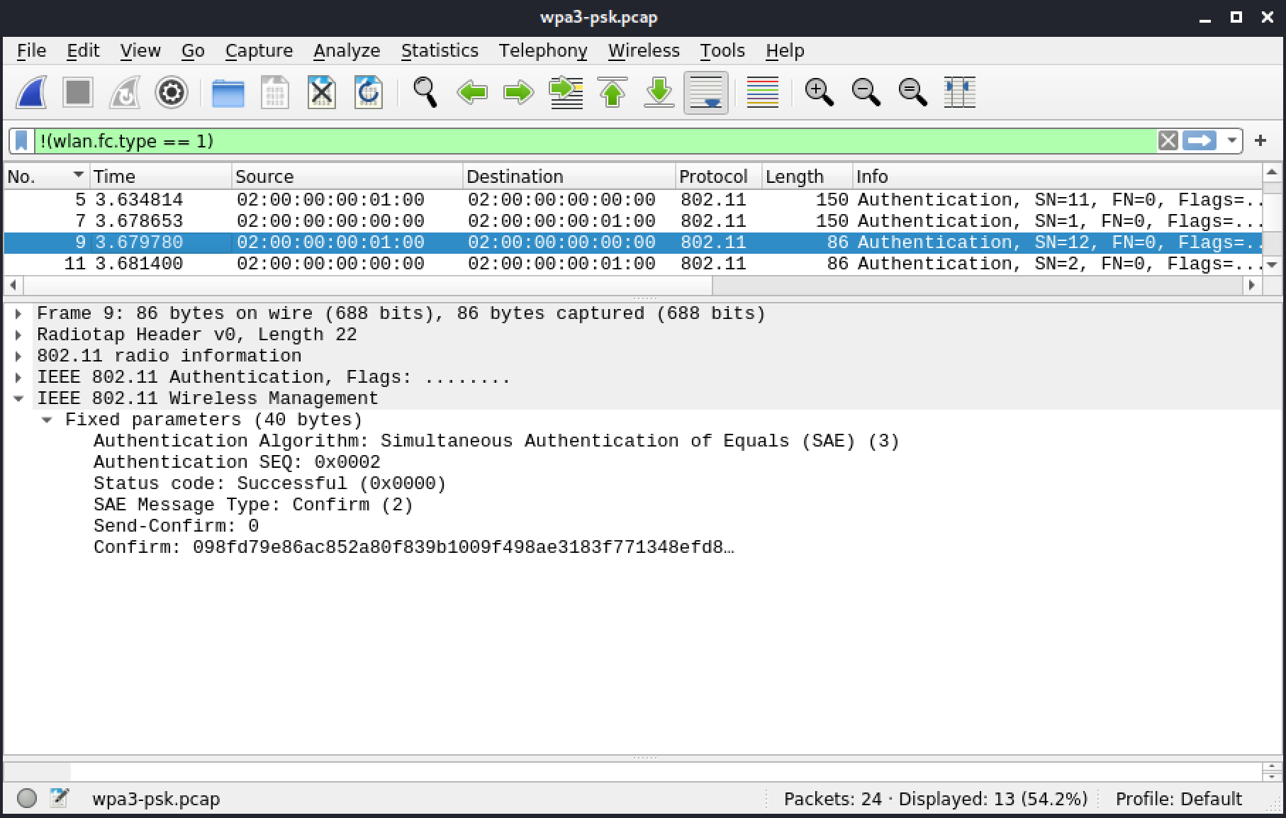
Figure 73: Frame 9: Authentication - Confirm message from client
And finally, in frame 11, there is an answer from the AP.
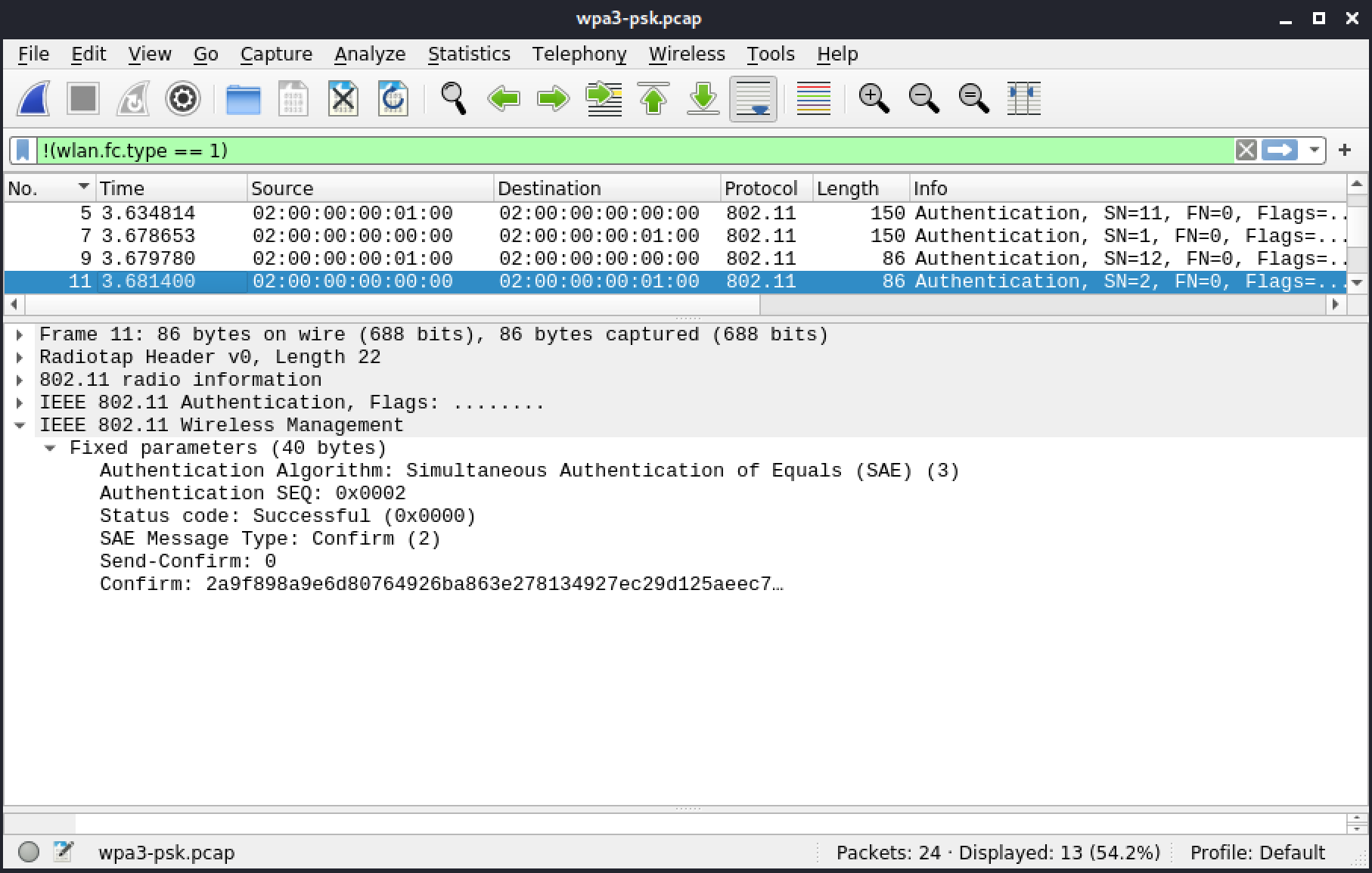
Figure 74: Frame 11: Authentication - Confirm message from AP
The association phase, which comes next, is uneventful. First the client indicates the specifics of the RSNA, including AES for unicast and multicast, SAE, and 802.11w.
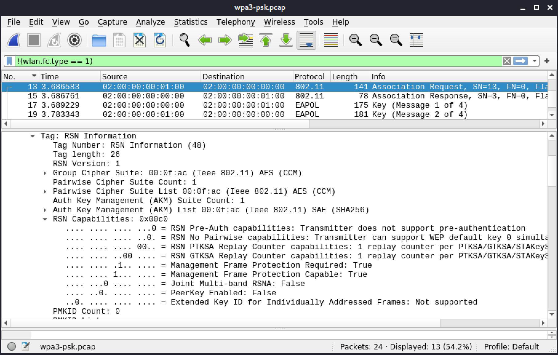
Figure 75: Frame 13: Association Request
Next, the AP sends the association response, accepting it.
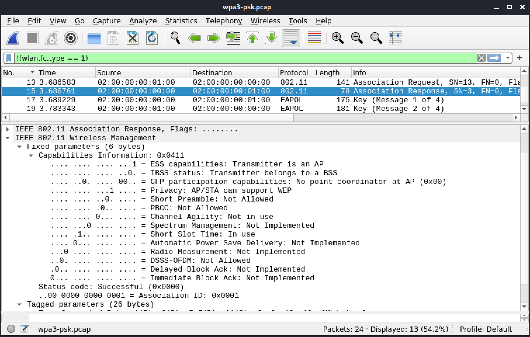
Figure 76: Frame 15: Association Response
The association stage concludes with the 4-way handshake, which uses AES/CCMP.
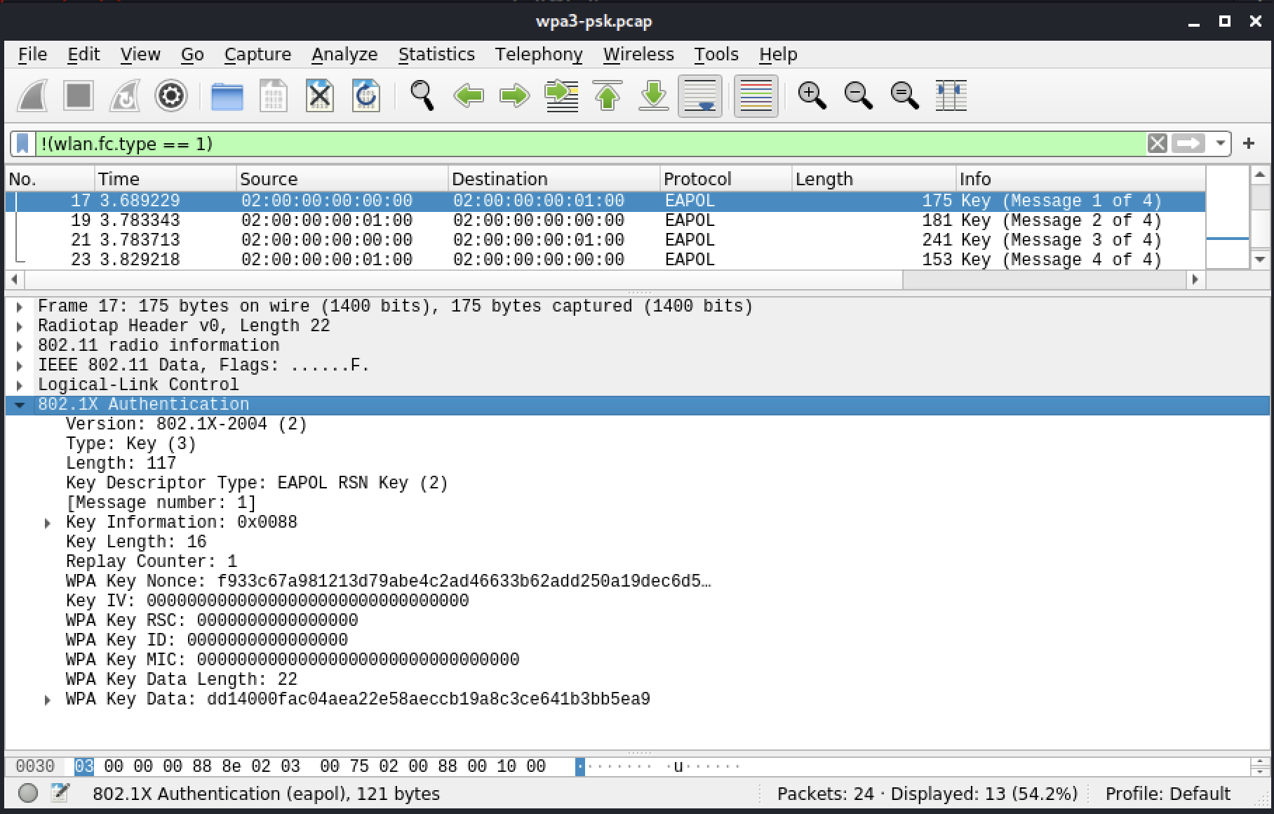
Figure 76: Frame 17: Association 4-way Handshake
5.4.7. Disagreeing on Group
[
Jump to resources to start virtual machines and/or answer labs
]
This section includes a reference file, wpa3-dh-group-disagreement.pcap, in the Resources section.
In most cases, a client and an AP will settle on the default group, 19. However, it is possible to configure groups on the AP and the client. In this section we'll explore a PCAP in which the client has a custom selection of groups that is different than what the AP would normally accept. The client will will go through the groups one by one until it finds one the AP can agree on.
Again, we'll use the !(wlan.fc.type == 1) display filter in Wireshark to skip over control frames that aren't relevant in this exchange.
The first frame is a beacon from the AP, advertising "WPA3-Network" with SAE and mandatory 802.11w.
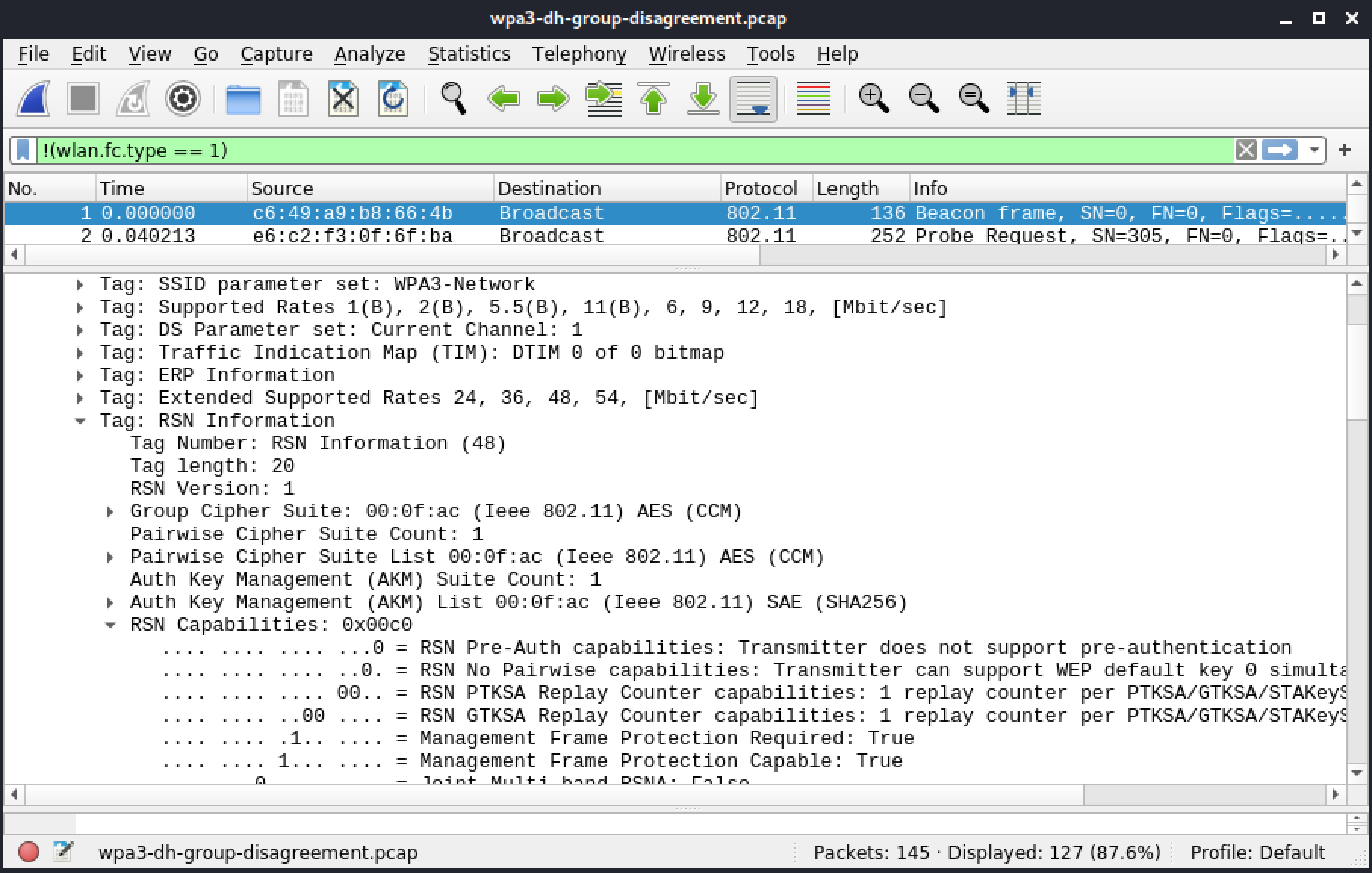
Figure 77: Frame 1: Beacon
The third frame is a response to the probe request with the same information as in the beacon.
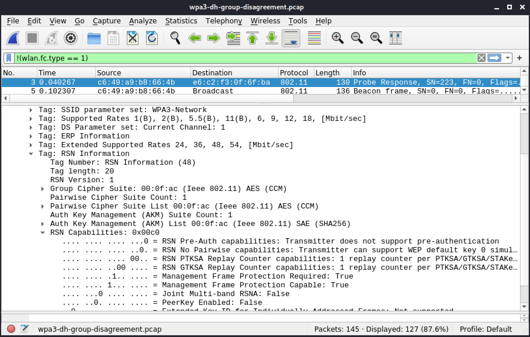
Figure 78: Frame 3: Probe response
The authentication for the dragonfly handshake starts at frame 51 where the client tries using group 15.
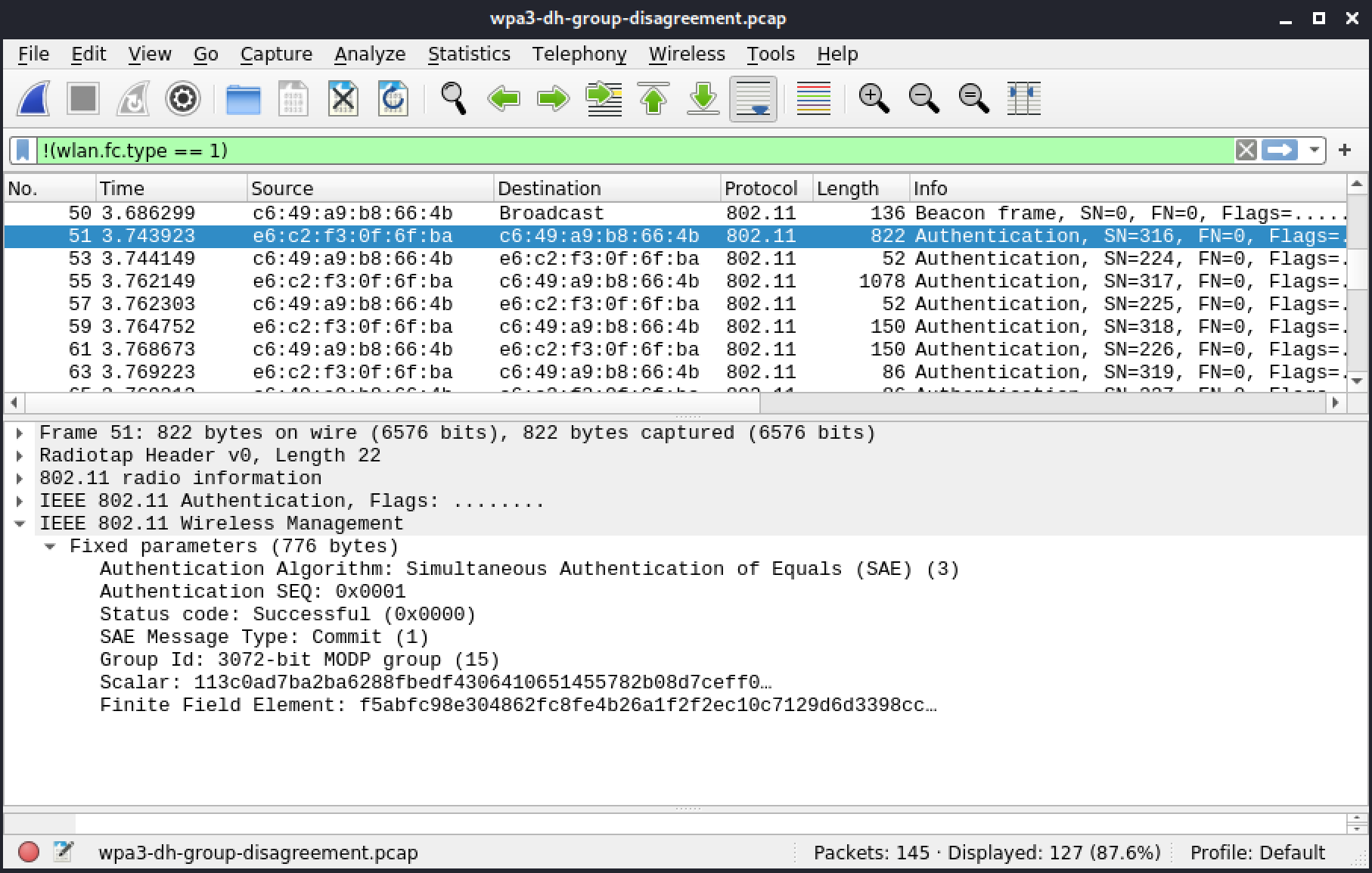
Figure 79: Frame 51: Authentication - client - group 15
The AP doesn't support group 15 and rejects it.
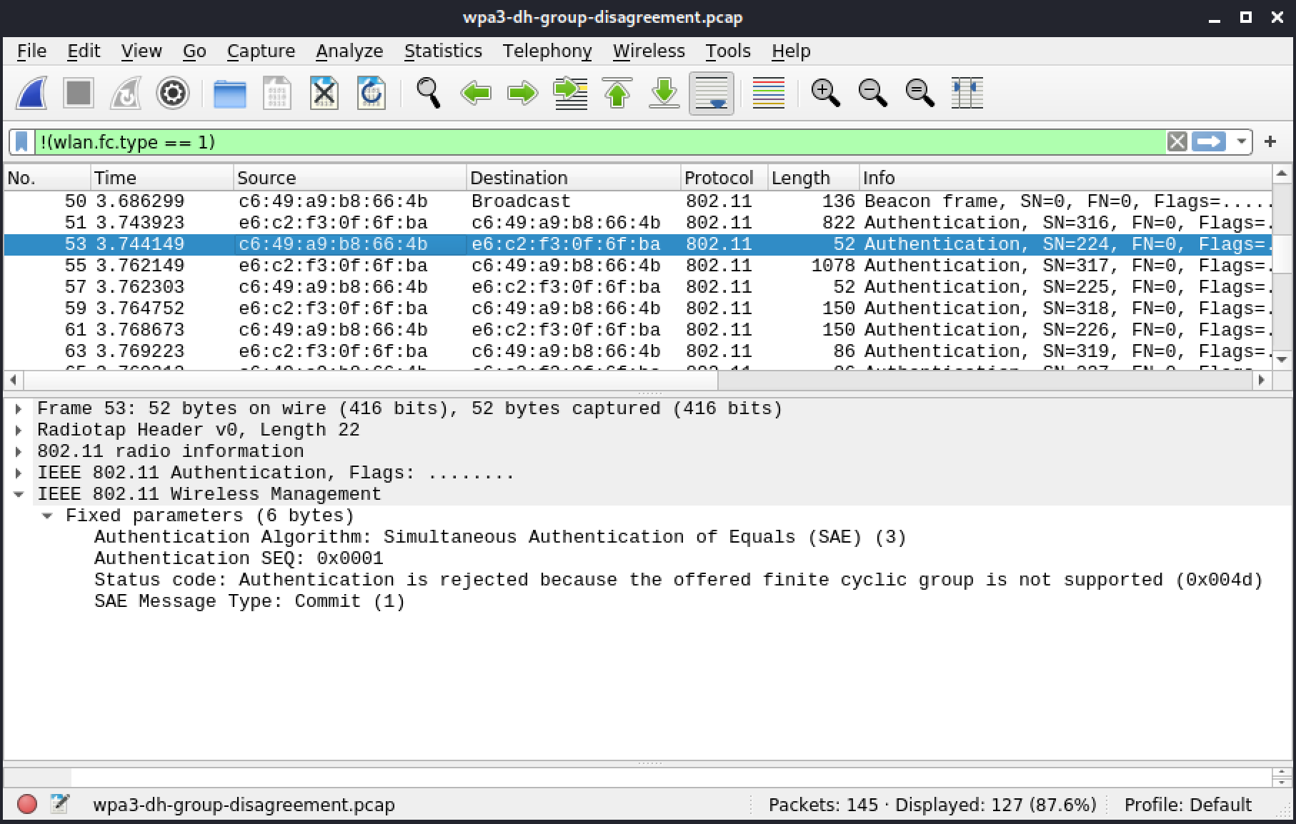
Figure 80: Frame 53: Authentication - AP - disagreeing group 15
Next, the client tries again. This time with group 16.
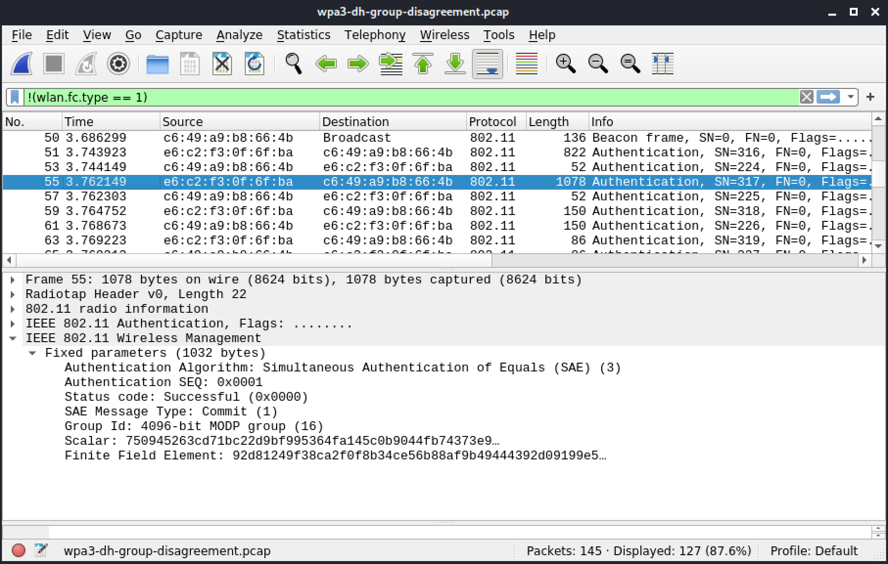
Figure 81: Frame 55: Authentication - client - group 16
The AP rejects this one as well.
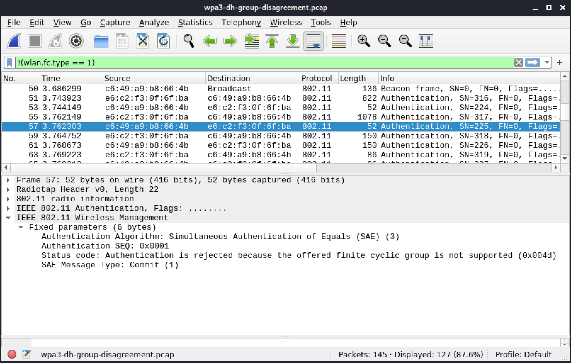
Figure 82: Frame 57: Authentication - AP - disagreeing group 16
Next, the client tries group 19.
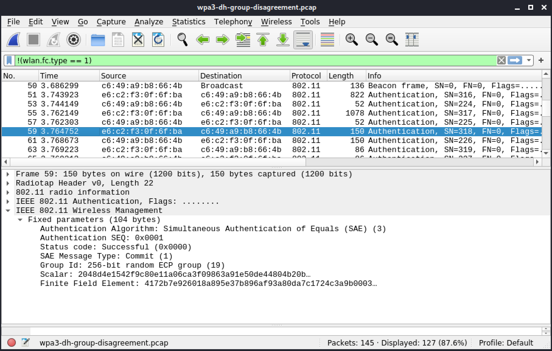
Figure 83: Frame 59: Authentication - client - group 19
Group 19 is the default group and is required in any implementation, so it will always be accepted.
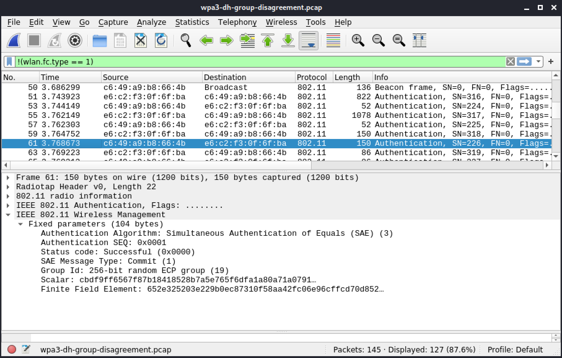
Figure 84: Frame 61: Authentication - AP - Accepting group 19
Now the client proceeds to the confirm phase.
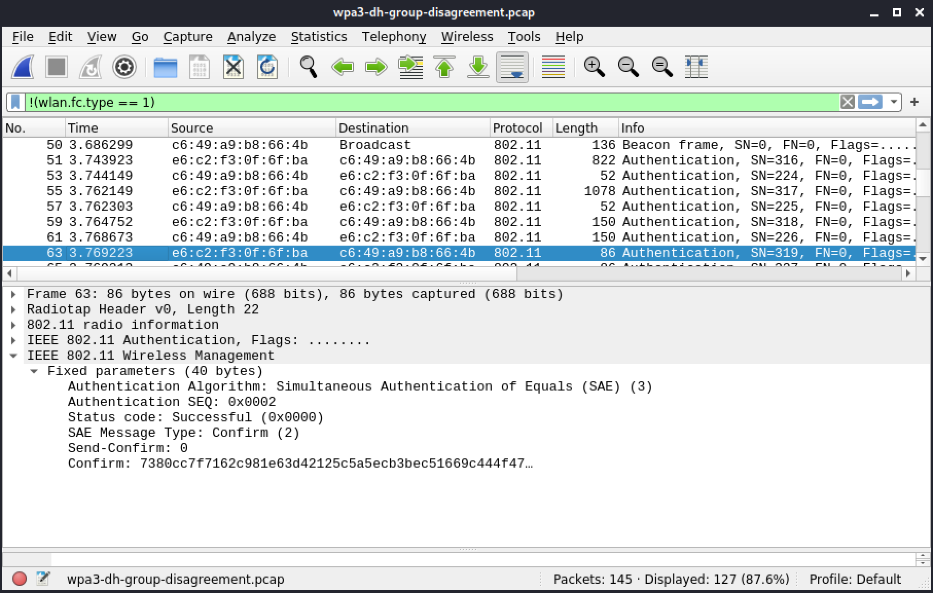
Figure 85: Frame 63: Authentication - Client - Confirm
The following frame from the AP concludes the authentication phase, which is successful, as indicated by the status code.
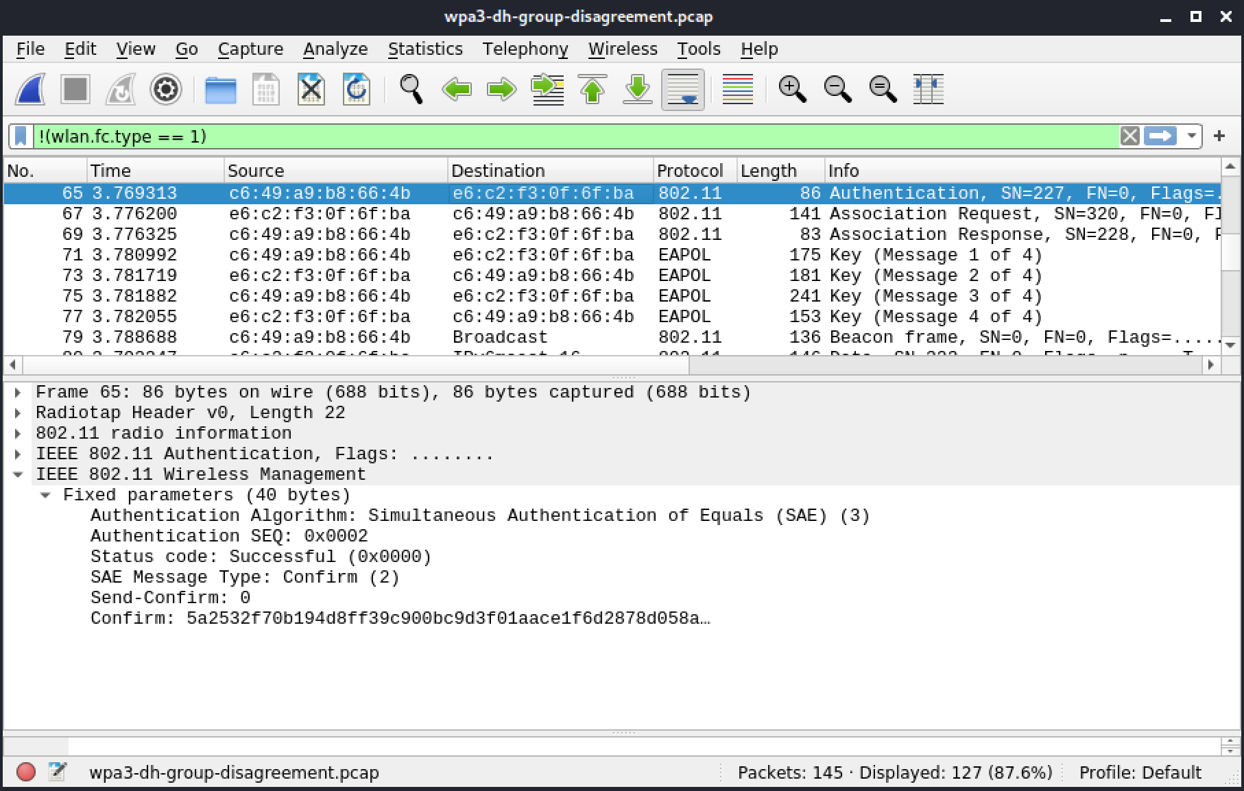
Figure 86: Frame 65: Authentication - AP - Confirm
From here, the client will associate to the AP and complete the 4-way handshake.
Resources
Some of the labs require you to download the file(s) below.
| Resource name | |
|---|---|
| wpa3-dh-group-disagreement.pcap | |
5.4.8. Opportunistic Wireless Encryption
[
Jump to resources to start virtual machines and/or answer labs
]
This section includes a reference file, owe.pcap, in the Resources section.
In this section we'll review a capture that contains a successful OWE association. Once again, we'll use !(wlan.fc.type == 1) to skip over control frames.
Frame 1 below shows a beacon with a RSN tag offering OWE only.
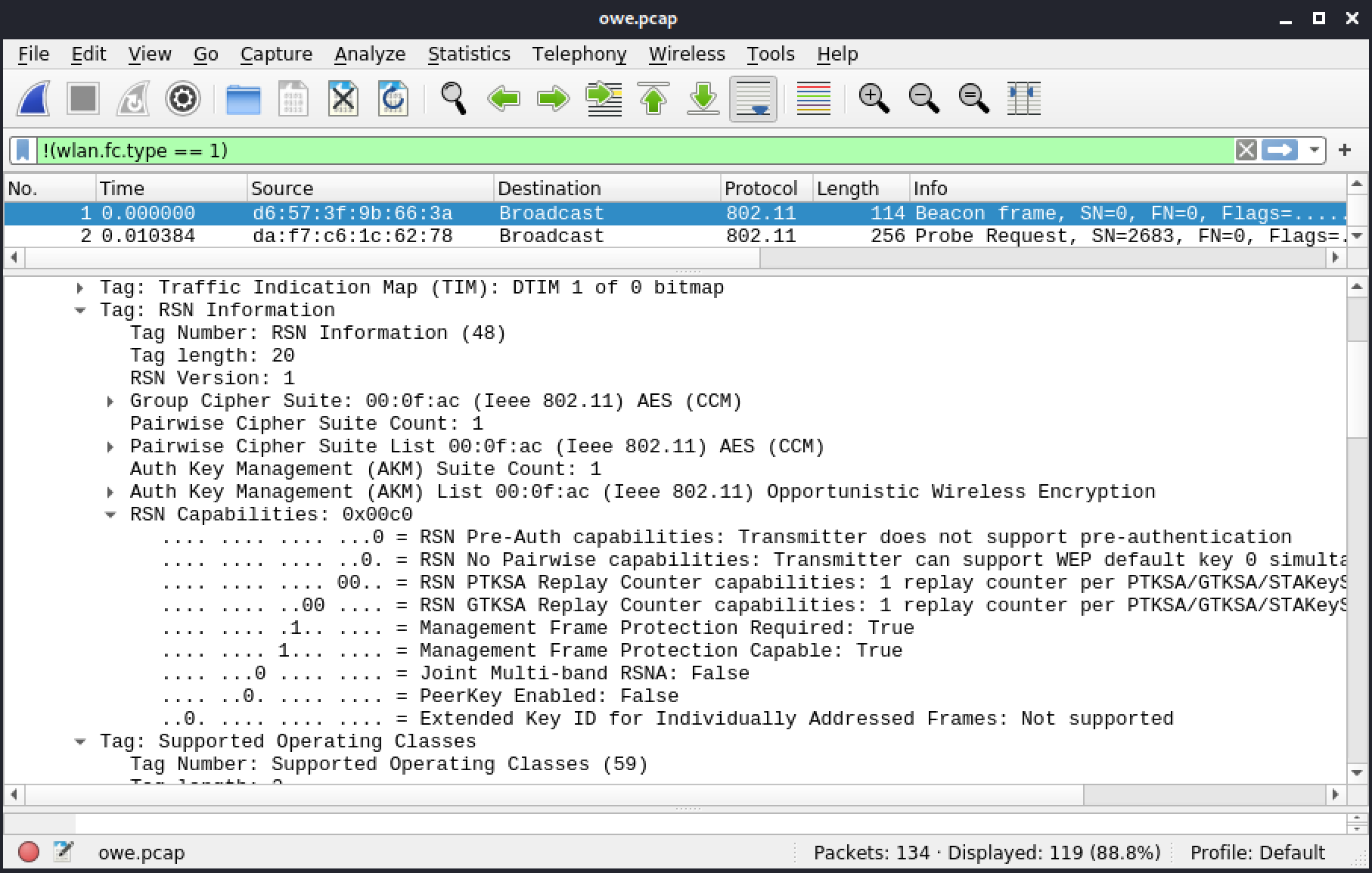
Figure 87: Frame 1: Beacon with RSN IE with OWE
Like WPA3, OWE requires 802.11w. This protects some management frames that are susceptible to attacks.
The following figure contains a client probe that also has an RSN IE with OWE, and 802.11w.
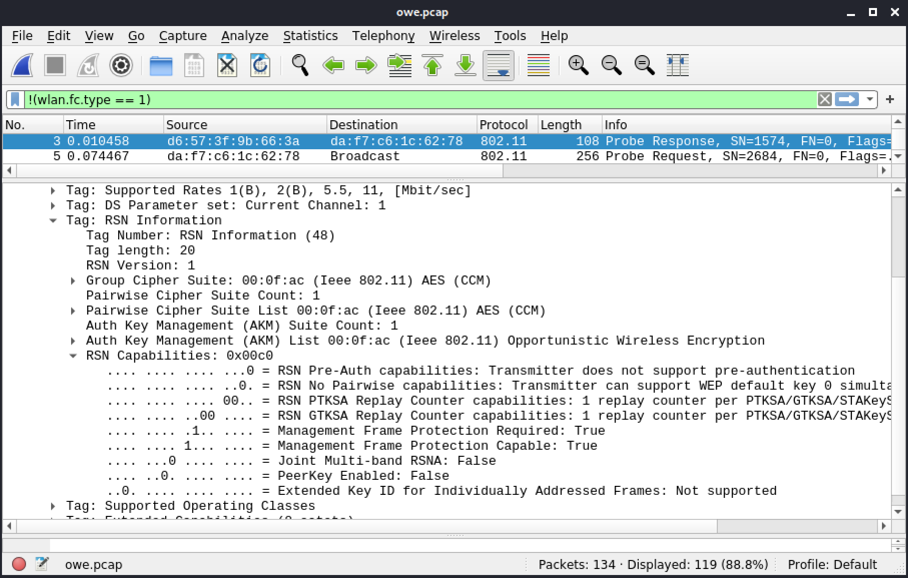
Figure 88: Frame 3: Probe response with RSN IE with OWE
The open authentication, with frames 51 and 52 from the client and the AP respectively, is uneventful. Whereas WPA3 used the authentication for the dragonfly handshake, OWE does public key exchange in the association phase. The association request from the client is in frame 55.
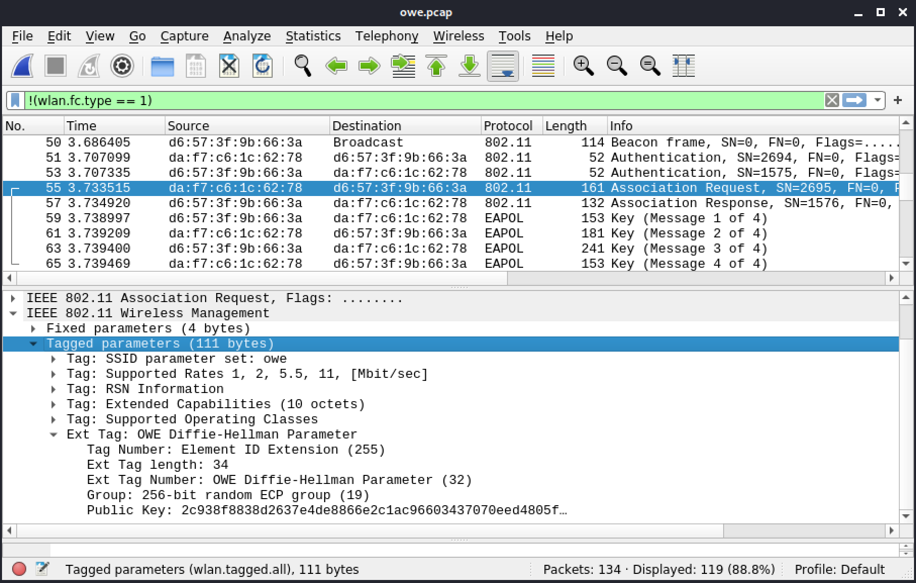
Figure 89: Frame 55: Association request
The last IE in the association request is an extended IE, which contains the Diffie-Hellman parameters from the client. These include the Diffie-Hellman group used, default group 19, and the public key.
In the following frame, the AP sends its information as well.
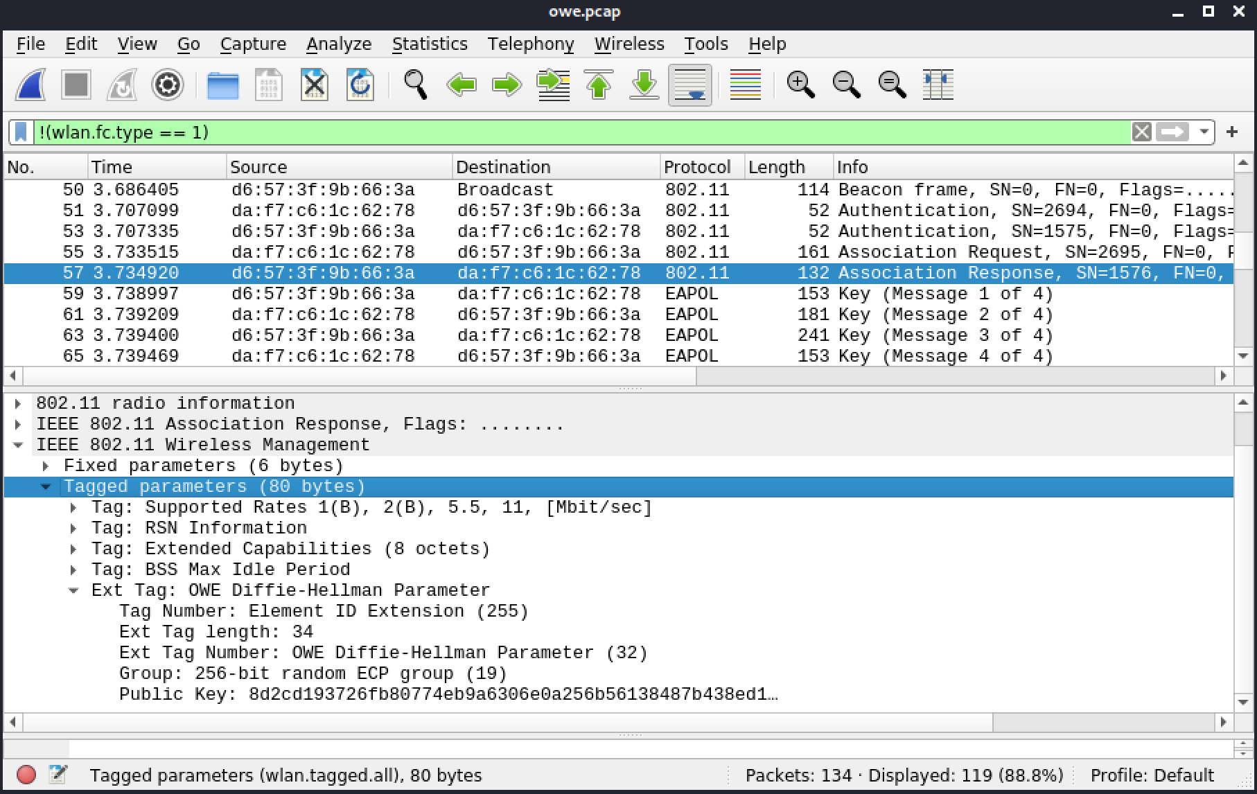
Figure 90: Frame 57: Association response
From there, they can both derive the same PMK for use in the 4-way handshake like in WPA2, in frame 59, 61, 63, and 65.
Resources
Some of the labs require you to download the file(s) below.
| Resource name | |
|---|---|
| owe.pcap | |
5.4.9. Wi-Fi Protected Setup
[
Jump to resources to start virtual machines and/or answer labs
]
This section includes a reference file, wpsdata.cap, in the Resources section.
This packet capture contains a successful WPS exchange. It has duplicate frames (frames with the retry bit set) because some frames were not acknowledged by the receiving device. When the ACK is not received within a specific amount of time, the frame it is supposed to acknowledge is assumed lost. The transmitter sends it again, however, this time the retry bit is set.
We will be using our !(wlan.fc.type == 1) display filter in Wireshark again.
Frame 1 below shows a beacon with the WPS tag.
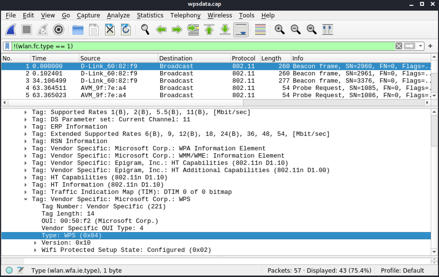
Figure 91: Frame 1: Beacon with WPS IE
Frames 4 to 16 (17 is a control frame and is not included) show the probe request from the client, the response from the AP, as well as the authentication and the association to the AP.
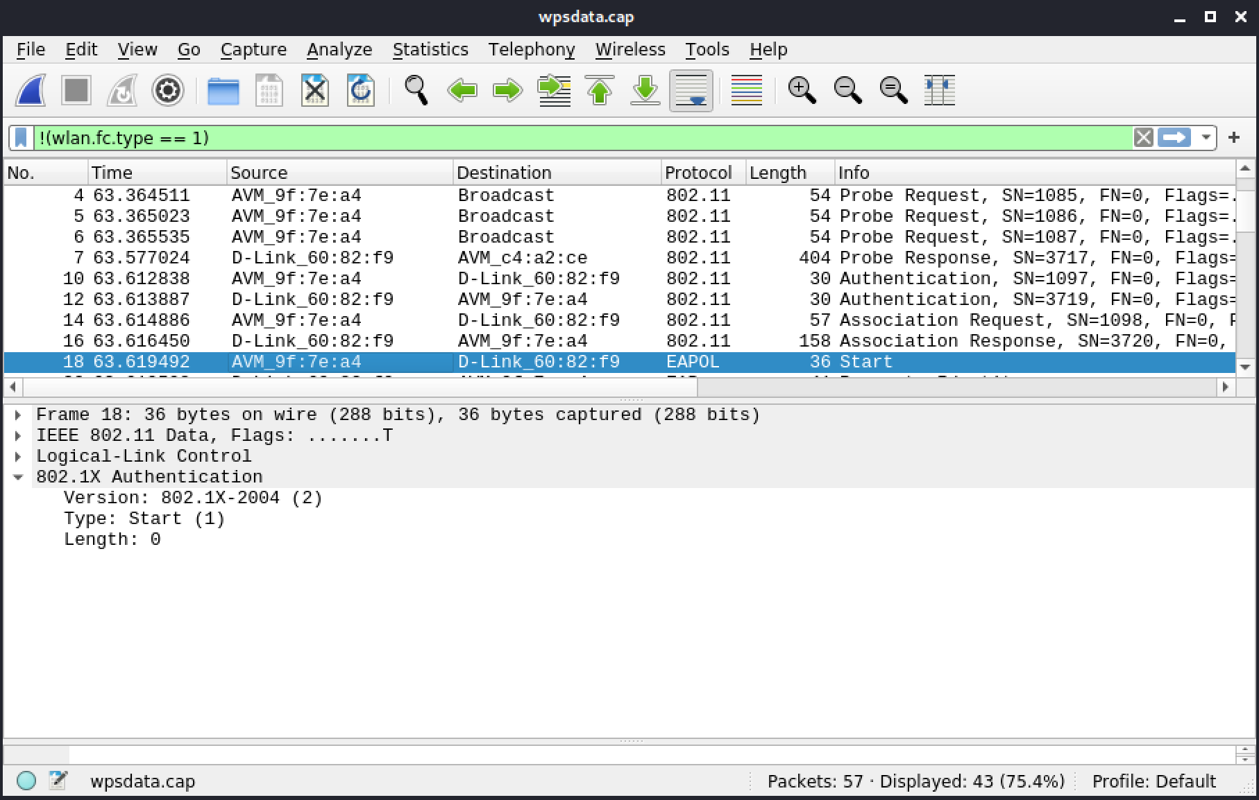
Figure 92: Frames 4 to 17: probing, authentication, association
Frame 18 includes the EAP Start from the client.
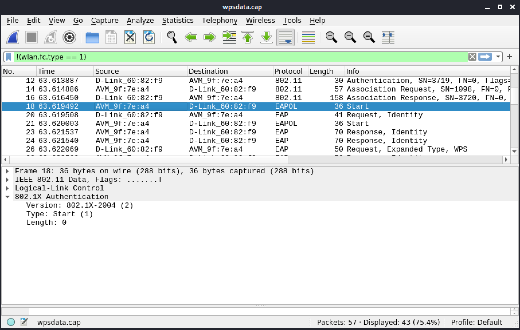
Figure 93: Frame 18: EAPoL start
Frame 20 includes the EAP Request Identity from the AP.
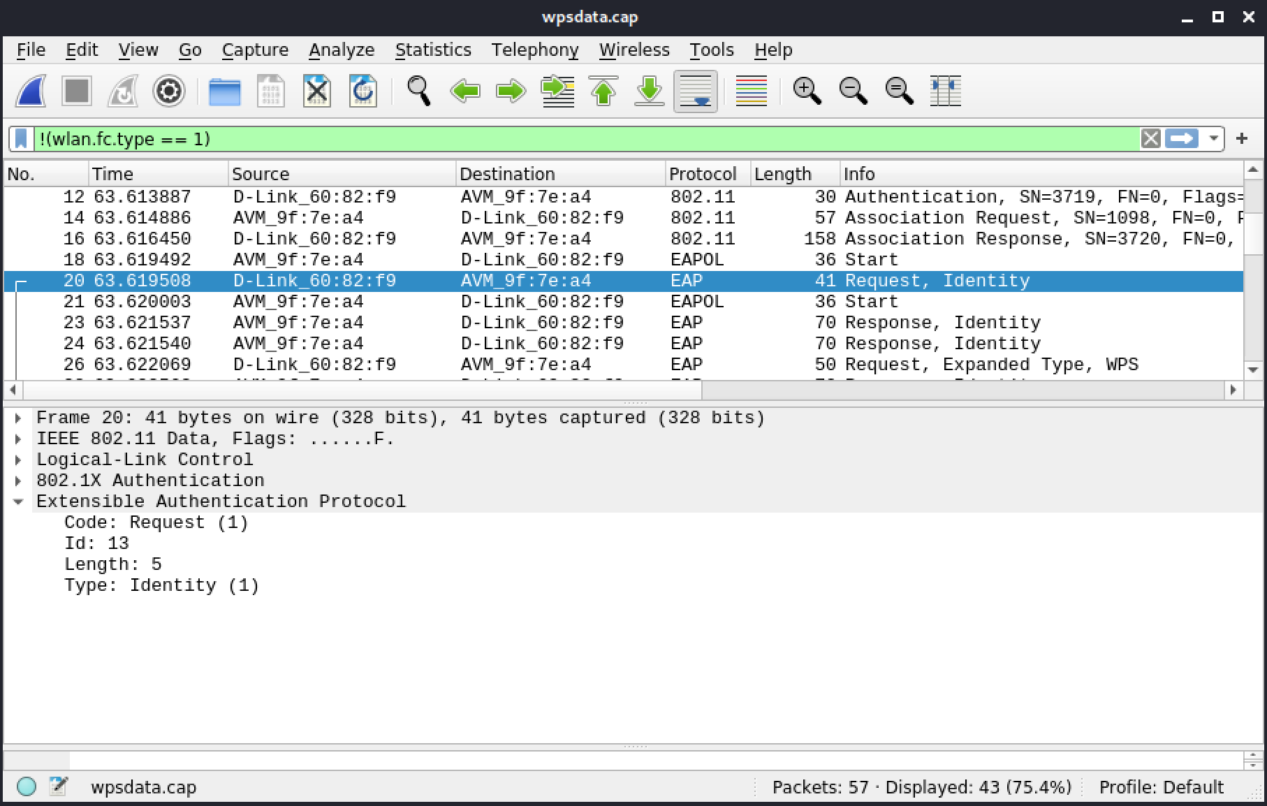
Figure 94: Frame 20: EAP Request Identity
After several retried frames, the identity response (with WFA-SimpleConfig-Enrollee-1-0) is frame 28.
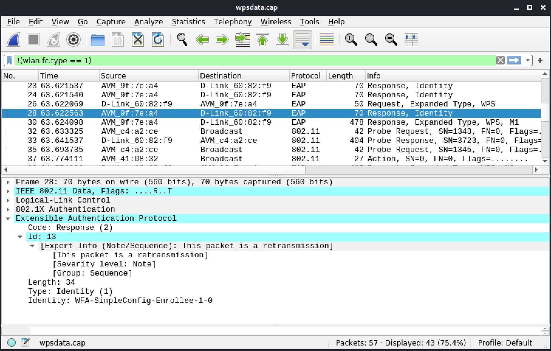
Figure 95: Frame 28: EAP Response Identity
Because of the retried EAP Response Identity, the request with WSC Start appears in frame 26, before the response.
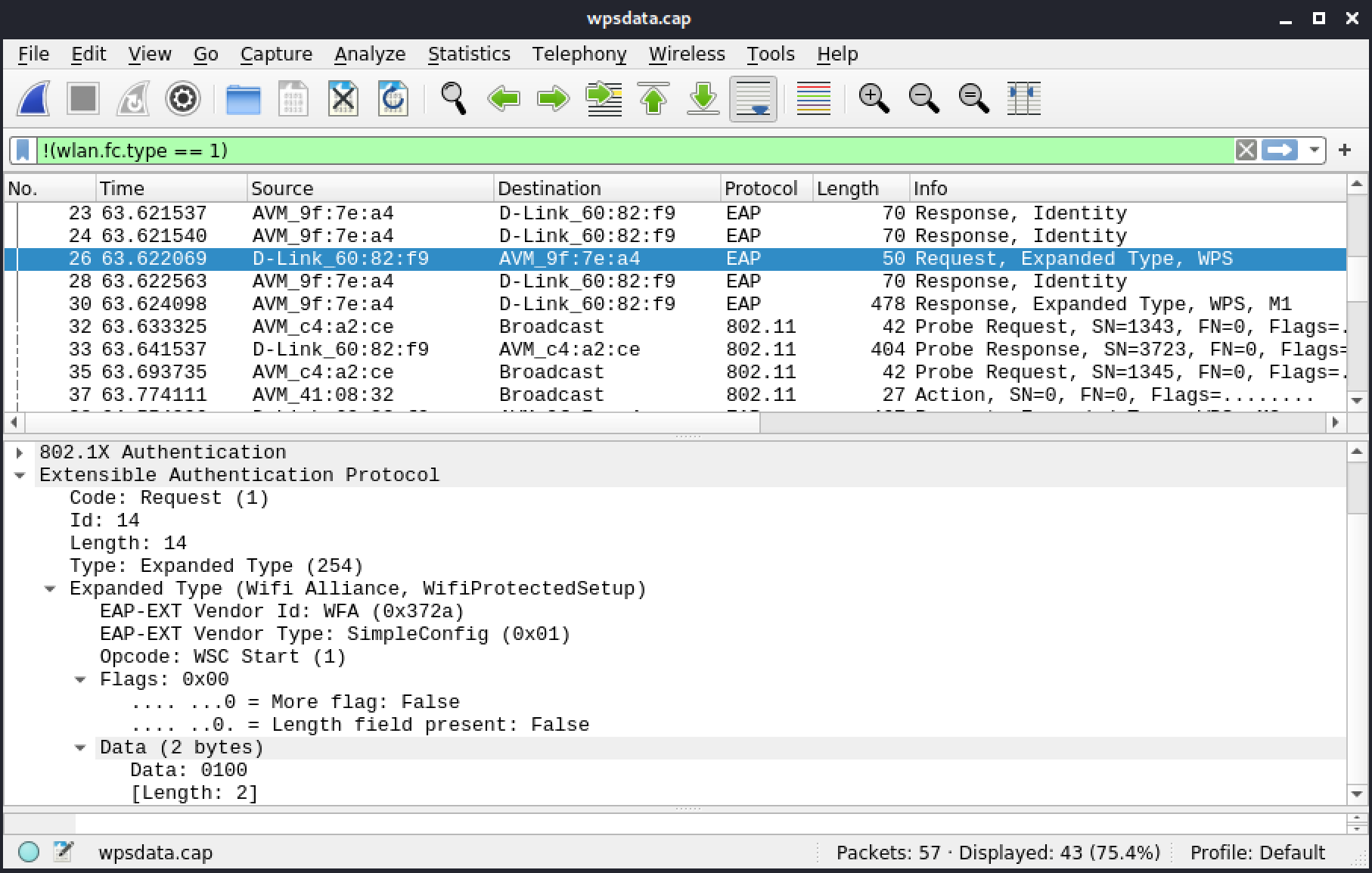
Figure 96: Frame 26: Request Expanded Types
The AP and the client will now exchange a series of eight messages called M1 to M8, sent in a sequential order, back and forth, to confirm the WPS PIN and securely exchange the passphrase, in M8. M1 includes information from the enrollee, and M2 will add registrar information. In WPS, the Registrar is an entity, not necessarily an AP, that can give access to the network. An enrollee is a device, most often either an AP or a client, looking to get the passphrase for the network. M1 (and M2 in a smaller measure) will help determine which is which.
Frame 30 shows M1 with detailed information about the enrollee, which includes the manufacturer of the wireless adapter (Atheros), the name of the device (WXP-JBRAEUER-T1), and the device password ID used. This last bit of information indicates, the type of password used (0000, default value), which indicates a PIN. Also included are the MAC address, nonce and public key (DH).
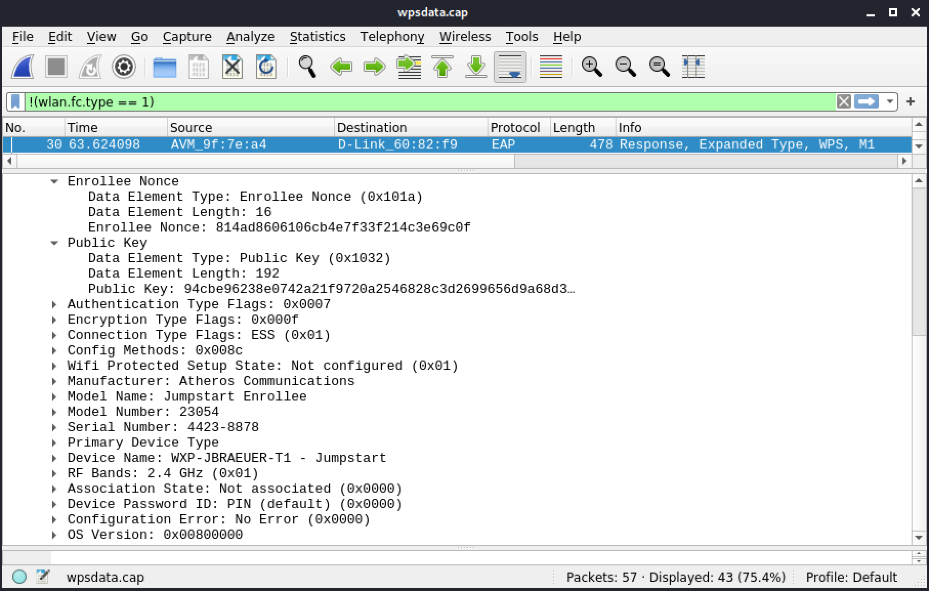
Figure 97: Frame 30: M1
Frame 38 shows M2 with information about the AP, a D-Link DIR-655 Model A1/A2. This frame also contains both the Enrollee and Registrar nonce as well as the public key (DH) of the Registrar.
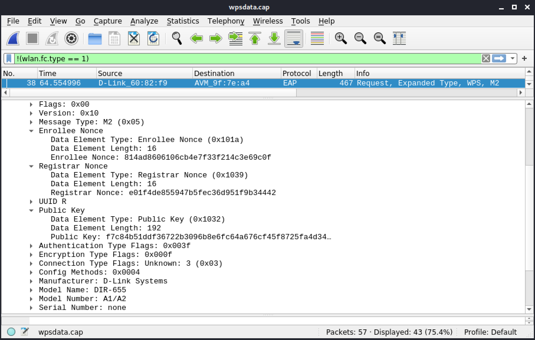
Figure 98: Frame 38: M2
Frame 42 below shows M3, which has been re-transmitted a few times (39, 40, 41, and 42) with the Registrar nonce and both E-Hash values (from the enrollee and the registrar).
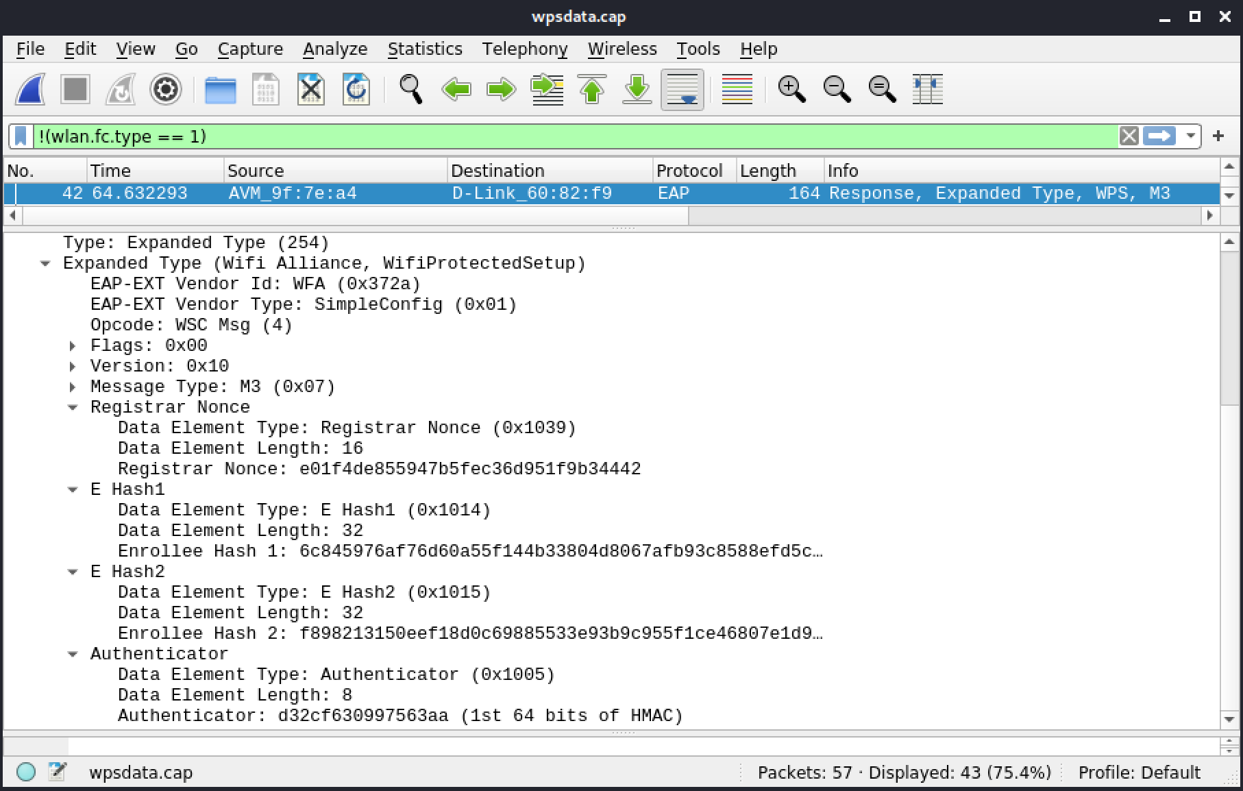
Figure 99: Frame 42: M3
Frame 43 below is M4 type with R-S1 encryption settings.
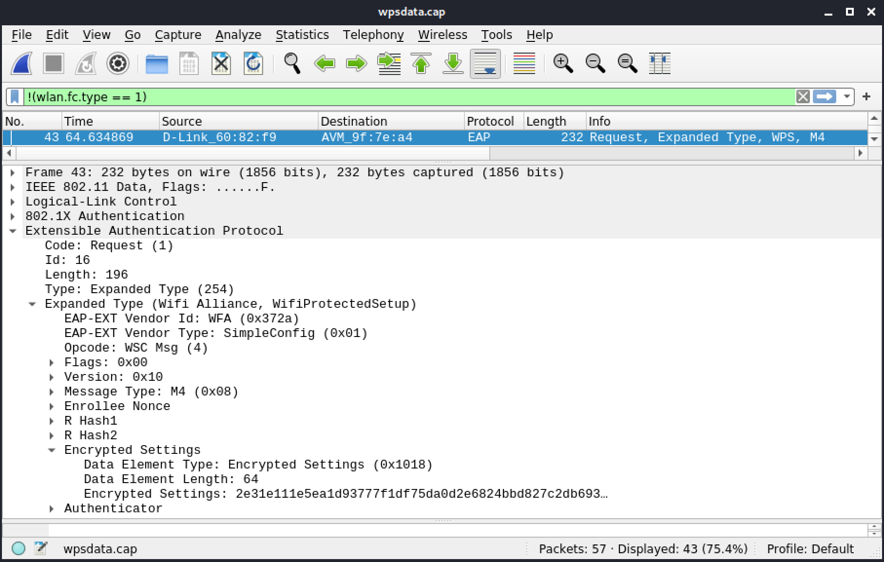
Figure 100: Frame 43: M4
The first half of the PIN has been validated.
Frame 44 is M5 type with E-S1 encryption settings. The second part of the PIN will be verified in the next few messages.
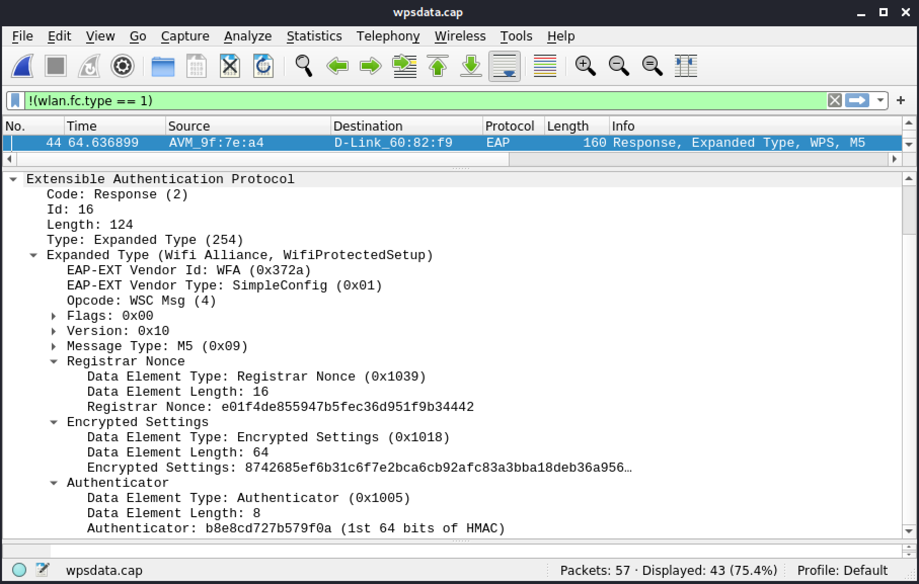
Figure 101: Frame 44: M5
Frame 45 is M6 type with R-S2 encryption settings.
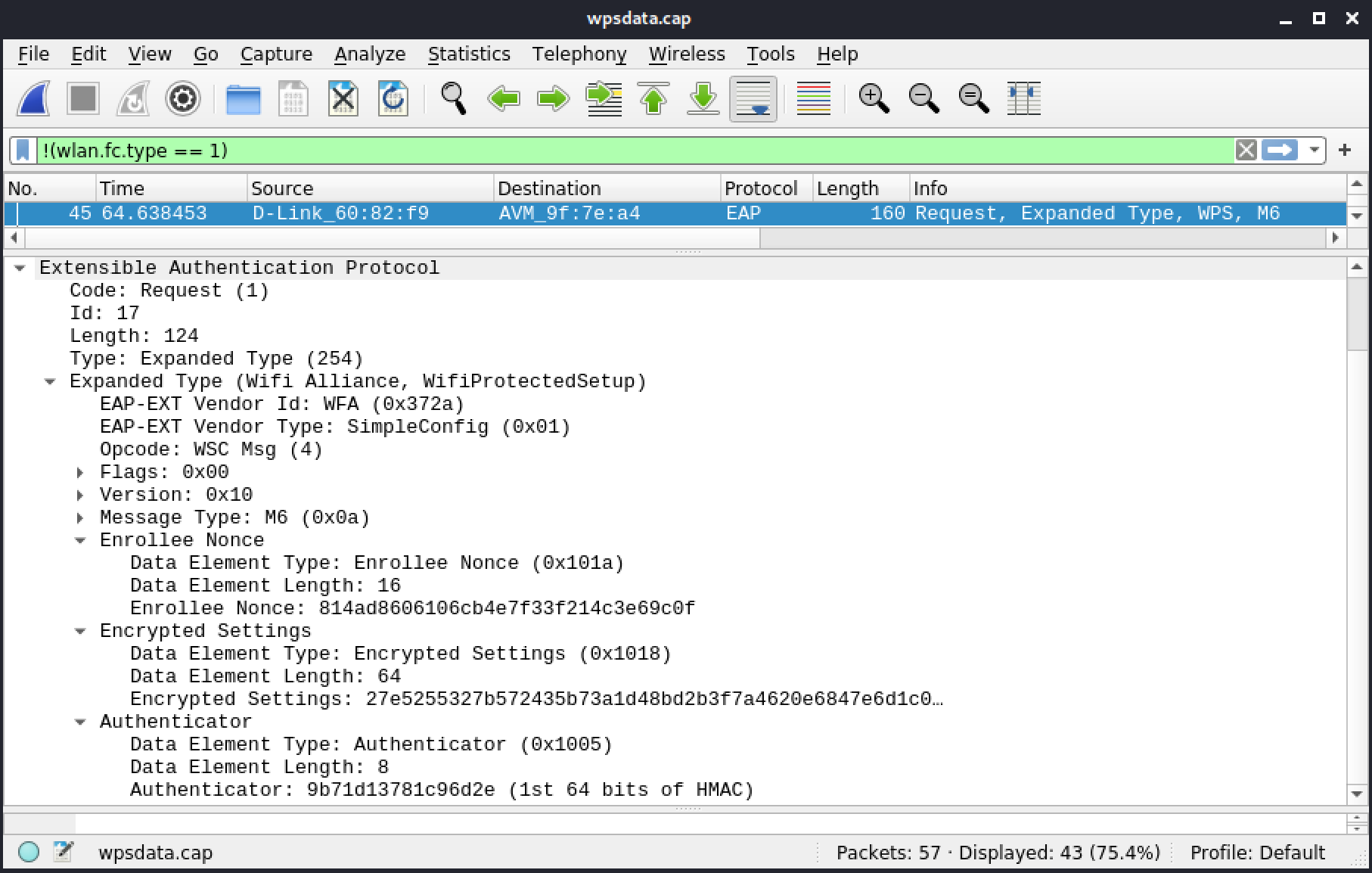
Figure 102: Frame 45: M6
Frame 46 is M7 type with E-S2 encryption settings.
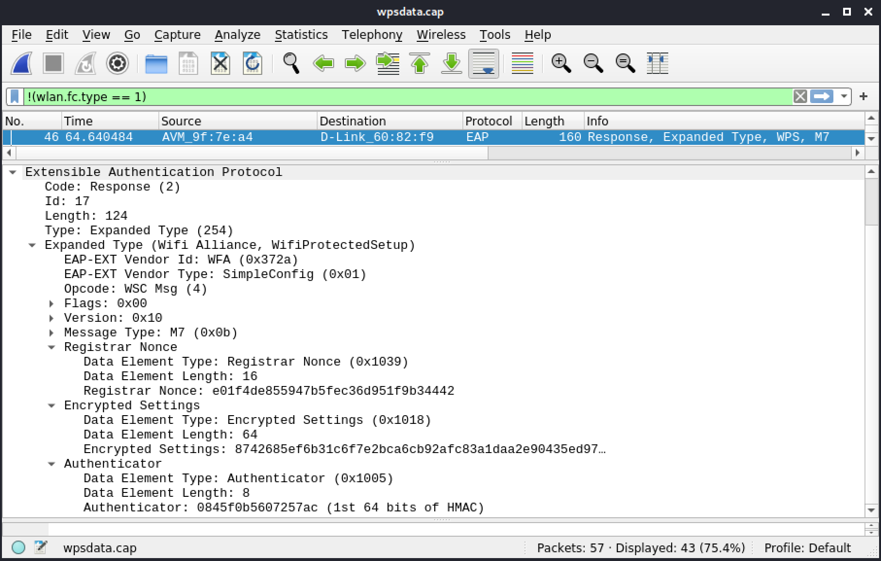
Figure 103: Frame 46: M7
Frame 47 below is M8 type with encrypted wireless settings for the Enrollee.
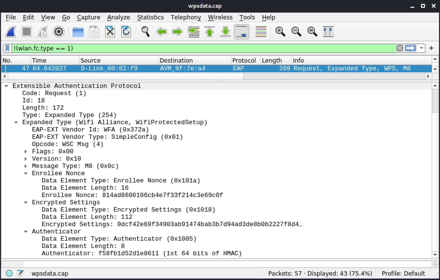
Figure 104: Frame 47: M8
WSC Done in frame 48 indicates the WPS (Wi-Fi Simple Configuration) exchange is finished.
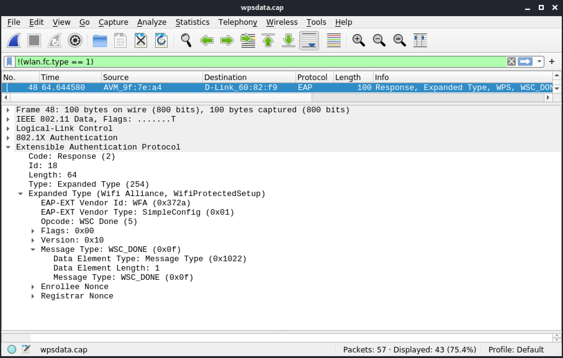
Figure 105: Frame 48: WSC Done
Frame 49 below shows EAP Failure to indicate the end of the registration protocol session, so now the client can now use the credentials to do the 4-way handshake:
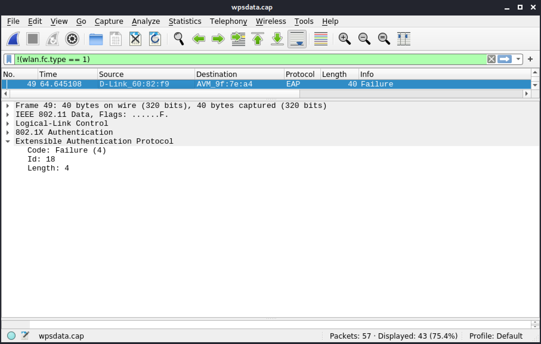
Figure 106: Frame 49: EAP Failure
Resources
Some of the labs require you to download the file(s) below.
| Resource name | |
|---|---|
| wpsdata.cap | |
5.4.10. 802.11w
[
Jump to resources to start virtual machines and/or answer labs
]
This section includes a reference file, pmf.pcap, in the Resources section.
This capture file shows the SA Query mechanism in action when 802.11w is negotiated by a client.
The first frame is a beacon. We notice that WPA2 CCMP is being used in the RSN IE (for both unicast and multicast frames). The Authentication Key Management (AKM) shows that pre-shared Key (PSK) is used. By default, SHA1 is used when Wireshark doesn't specify anything (AKM type with a value of 2), but in this case, 802.11w uses SHA256 (AKM type with a value of 6).
When RSN Capabilities are expanded, only the "Management Frame Protection Capable" bit is set, and thus the AP can accept clients with and without 802.11w.
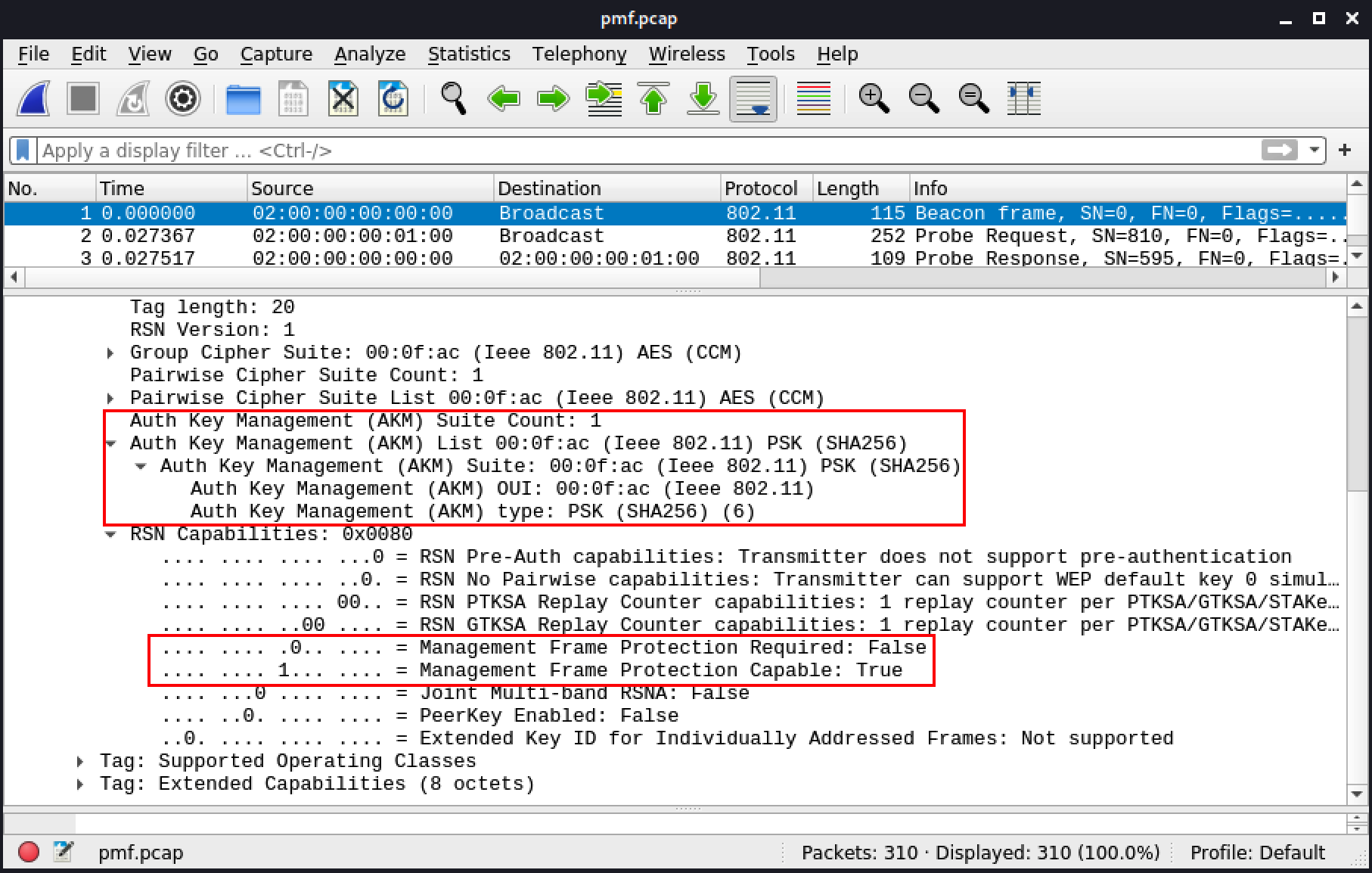
Figure 107: Frame 1: Beacon
The following few frames include several Probe Requests, in which the client is scanning for APs. Frame 3 shows a response from the AP with similar information as in the Beacon described in Figure 107.
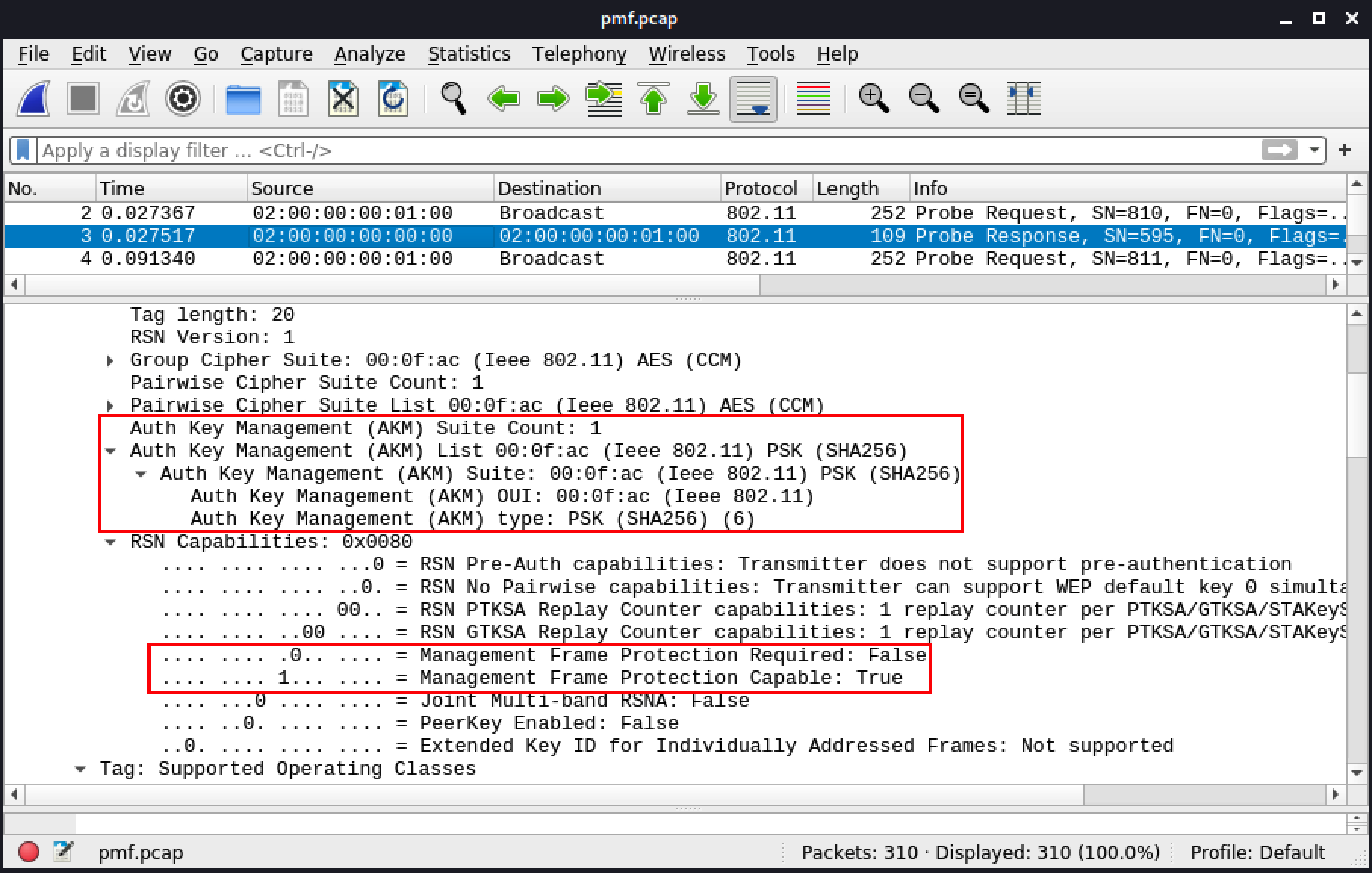
Figure 108: Frame 3: Association Response
Authentication starts at frame 50. The AP responds with frame 51, and the client then associates to the AP in frames 52 and 53. In frame 52, the association request, the client indicates it supports the AKM requested by the AP as well as PMF. With these settings, the client will only associate to an AP that either is set to "Capable" or "Required".
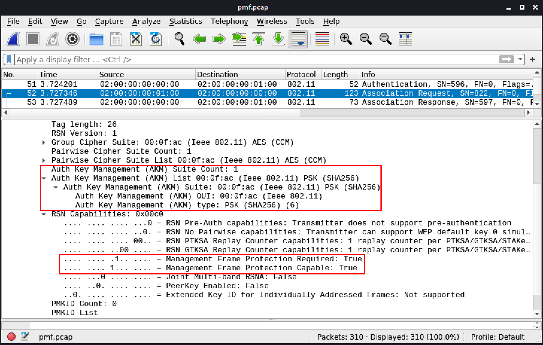
Figure 109: Frame 52: Association Request
The 4-way handshake is similar to any other WPA2 handshake.
Frame 132 is a deauthentication sent by an attacker. It is followed by two action frames and then more deauthentication frames. This could be a containment from a Wireless Intrusion Prevention System (WIPS), but in this case it is deauthentication attack from aireplay-ng.
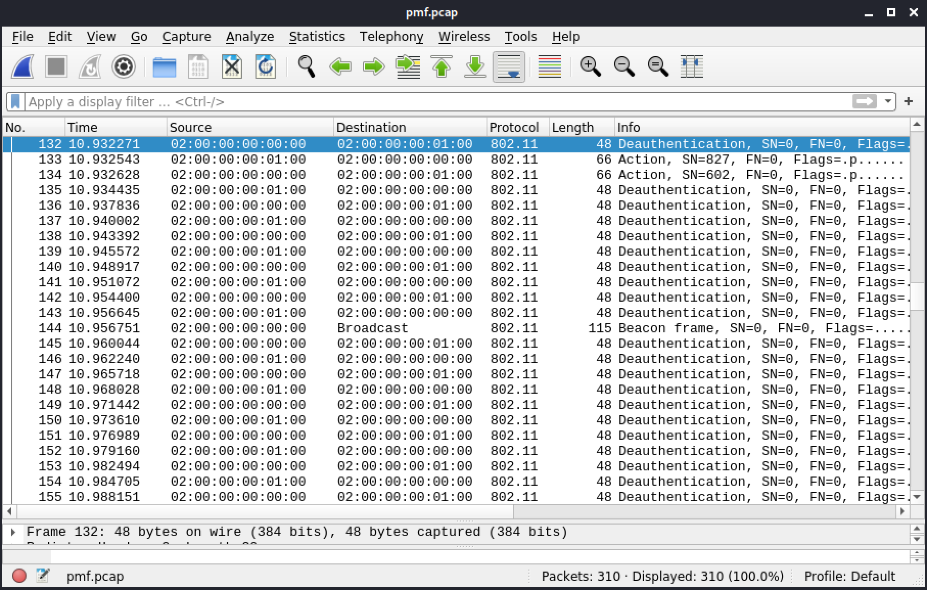
Figure 110: Frame 132: Deauthentication from an attacker
The first action frame (Figure 111) is an encrypted SA Query from the client, checking on the AP.
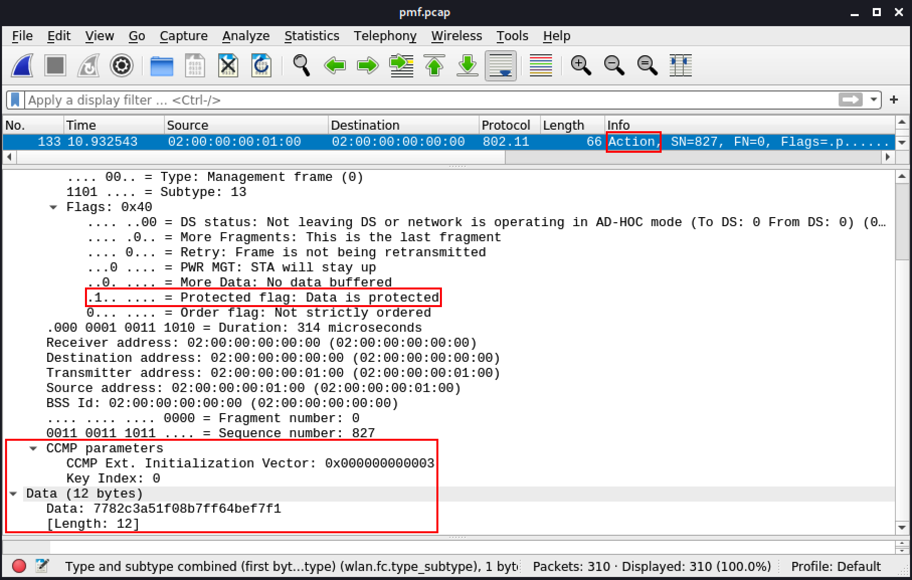
Figure 111: Frame 133: Action frame: SA Query
The AP responds immediately in frame 134. As a result, the AP will ignore deauthentications that do not come directly from the client.
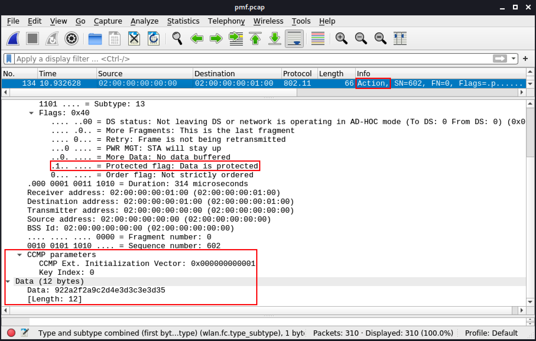
Figure 112: Frame 134: Action frame: SA Query response
Finally, the client sends a deauthentication frame when disconnecting from the network so the AP can free resources associated to the client's connection.
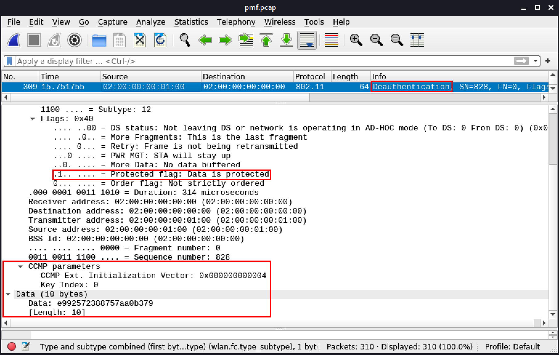
Figure 113: Frame 309: Deauthentication from the client
5.5. Wrapping Up
In this module, we first went over the 802.11 frame structure, and explored the details of common frames encountered on Wi-Fi networks. We then learned how these frames work together when connecting to networks with different encryption types.