1. The IEEE 802.11 Standard
In this module we will introduce the wireless communication terminology and concepts described by the various IEEE 802.11 protocols. Every wireless card supports a specific 802.11 protocol and may or may not be able to work with others.
It's useful to understand these protocols because we will be highly dependent on the hardware we use as well as on the equipment used in the testing environment. It's easy to imagine how understanding a piece of hardware can help us use it correctly. To that end, this module serves two purposes.
First and foremost, we want to provide an overview of these protocols and the differences between them. We don't expect anyone to memorize the information here but knowing which standard our device supports and what frequencies it covers is important.
Consider this quick example. If we are trying to capture packets from an 802.11ac transmitter, a basic understanding of beamforming and streams could be helpful if we are having problems.
The second purpose of this module is to serve as an abbreviated reference guide. Again, there are a lot of terms and concepts here, and we can't memorize them all. In general, when we encounter a new piece of hardware, we may choose to return to this module for a quick review.
1.1. IEEE
The Institute of Electrical and Electronics Engineers (IEEE) is a group of over 423,000 scientists, engineers, and other professionals who are the leading authorities in aerospace, telecommunications, biomedical engineering, electric power, and more.
The IEEE's 802 committee develops Local Area Network (LAN) standards and Metropolitan Area Network (MAN) standards. These include Ethernet, Token Ring, Wireless LAN, Bridging, and Virtual Bridged LANs.
1.2. 802.11 Standards and Amendments
IEEE 802.11 is the standard for wireless LAN (WLAN). The specifications cover the physical layer and the Media Access Control (MAC) section of the data link layer in the OSI model.
The 802.11 committee has released amendments to the standards as wireless technology has advanced. We will cover the amendments listed below:
- 802.11: The original WLAN standard
- 802.11a: Up to 54 Mbit/s on 5 GHz
- 802.11b: 5.5 Mbit/s and 11 Mbit/s on 2.4 GHz
- 802.11g: Up to 54 Mbit/s on 2.4 GHz, backwards compatible with 802.11b
- 802.11h: Regulatory requirement to limit power and transmission in the 5GHz band
- 802.11i: Provides enhanced security
- 802.11n: Provides higher throughput with Multiple Input/Multiple Output (MIMO), aka Wi-Fi 4
- 802.11ac: Very High Throughput (VHT) < 6 GHz, aka Wi-Fi 5
- 802.11ad: Multi-Gigabit in the 60 GHz band, known as WiGig
- 802.11ax: High Efficiency (HE) Wireless LAN, aka Wi-Fi 6
- 802.11ax (6 GHz extension): Operates in the 6 GHz band, marketed as Wi-Fi 6E
- 802.11be: Extremely High Throughput (EHT), aka Wi-Fi 7 (ratified 2024)
1.2.1. IEEE 802.11
The original IEEE 802.11 standard, released in 1997, defines the 1 and 2 Mbit/s data rates over radio frequencies using Direct-Sequence Spread-Spectrum (DSSS) and Frequency Hopping Spread-Spectrum (FHSS). It is often called pure-802.11.
Both of these modulations are spread spectrum, which deliberately spreads the transmission. This provides better resistance to noise, interference, and jamming. When DSSS is in use with 802.11, channels will be 22MHz wide. FHSS, as the name suggests, hops across its allocated bandwidth. Technologies like GPS and Zigbee make use of DSSS whereas Bluetooth is known for using FHSS.
Consider a simple, everyday conversation. Problems can occur when people try to talk and listen at the same time or when several people are talking at once. There are similar issues with Wi-Fi and in general for any wireless technology.
Transmitting simultaneously presents a problem when traffic "steps on" other traffic. We generally refer to this as a collision. It isn't possible to spot collisions. They are indistinguishable from interference or noise. In some cases, these collisions happen farther away, and as a result, they are not detectable by the transmitter.
Like most other wireless technologies, Wi-Fi radios can either receive or transmit, but cannot do both simultaneously. This functional limitation is why we refer to Wi-Fi radio as half duplex. If two or more radios transmit at the same time, they have no way of knowing if their transmission went through or collided, so the best that can be done is trying to avoid collisions.
IEEE 802.11 uses Carrier Sense Multiple Access with Collision Avoidance (CSMA/CA) before transmitting. Before a system on a CSMA/CA network transmits data, it will first listen for a predetermined amount of time to ensure no other system is transmitting. This is the Carrier Sense (Multiple Access) protocol. If the system hears traffic, it will wait before restarting this process. This is the Collision Avoidance protocol.
Sometimes, two or more nodes may try to communicate with the access point but are too far from each other and cannot hear each other's traffic. Applying CSMA/CA, the channel may become free for both at the same time, and both will transmit. However, this results in interference at the access point. This is called a hidden node problem.
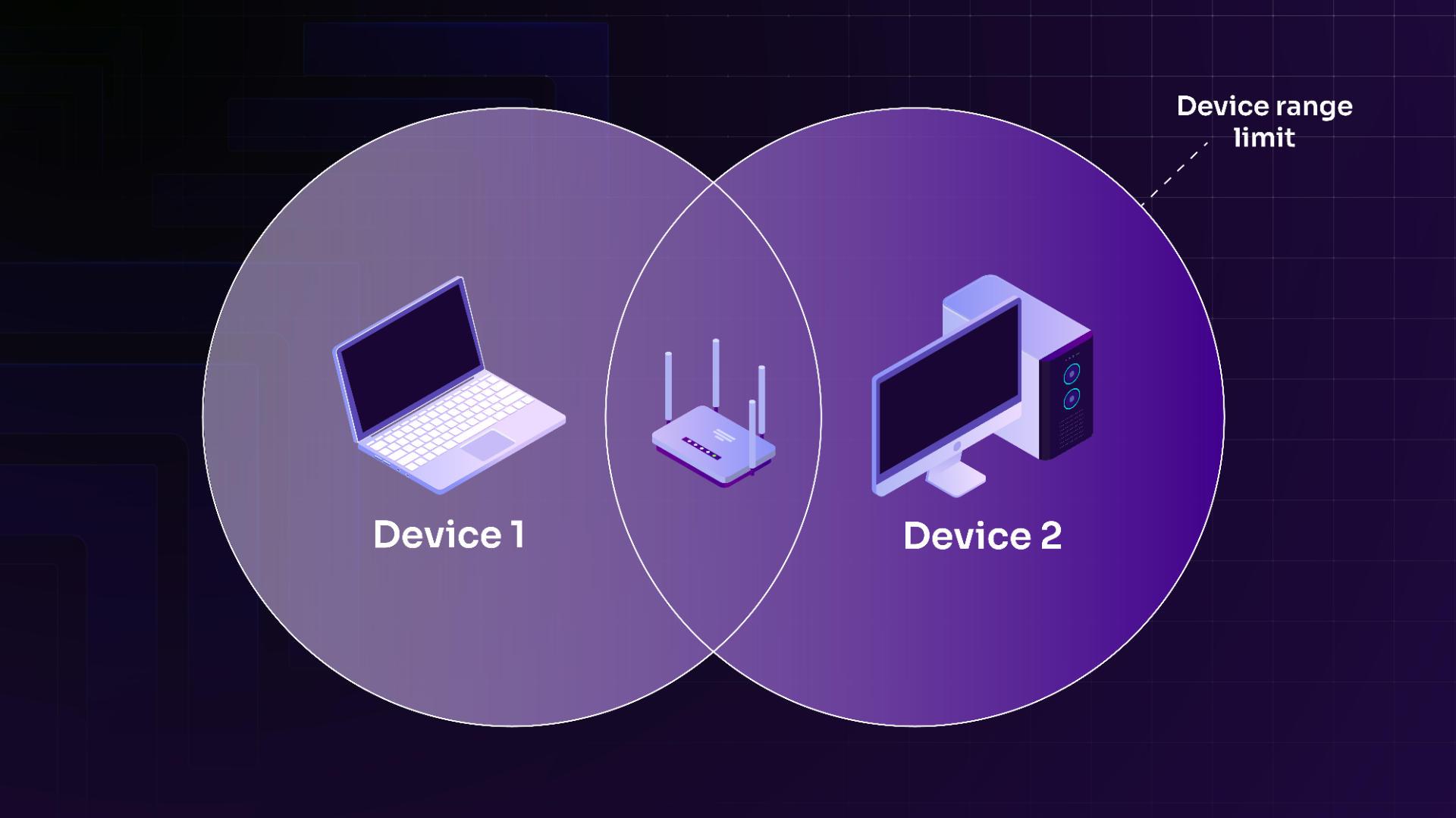
Figure 1: Hidden Node Problem
As the name implies, CSMA/CA tries to avoid collisions, but cannot always avoid them. It can be supplemented with the Request to Send/Clear to Send (RTS/CTS) mechanism to improve the odds of avoiding a collision.
Using RTS/CTS, stations send an RTS, which is acknowledged by a CTS by the access point. Once the station receives the CTS, the data is exchanged. In the hidden node problem scenario, both stations that are in range of the access point (but out of range of each other) receive the CTS, but only the station mentioned in the CTS transmits.
1.2.2. IEEE 802.11b
The IEEE 802.11b amendment added Complementary Code Keying (CCK), providing 5.5 and 11 Mbit/s rates on the 2.4 GHz band (operating from 2.4 GHz to 2.485 GHz) on 14 channels.
Figure 2 provides a visual representation of the 802.11b channels across the 2.4GHz frequency range.
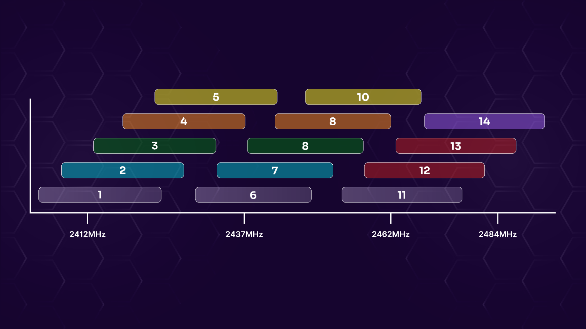
Figure 2: 802.11b channels
Each channel is 22 MHz wide, and as evidenced by this figure, there is only enough spectrum for three non-overlapping channels in this frequency range.
As with any other wireless equipment, when referring to a channel frequency, we are always referring to its center frequency. The center frequency is the frequency in the center of a channel's bandwidth. For example, the range for channel 1 is 2.401 GHz to 2.423 GHz, but the we refer to its frequency as 2.412 GHz, which is at the center of this range.
Table 1 lists the center frequency of each channel.
| Channel | Center Frequency |
|---|---|
| 1 | 2.412 GHz |
| 2 | 2.417 GHz |
| 3 | 2.422 GHz |
| 4 | 2.427 GHz |
| 5 | 2.432 GHz |
| 6 | 2.437 GHz |
| 7 | 2.442 GHz |
| 8 | 2.447 GHz |
| 9 | 2.452 GHz |
| 10 | 2.457 GHz |
| 11 | 2.462 GHz |
| 12 | 2.467 GHz |
| 13 | 2.472 GHz |
| 14 | 2.484 GHz |
Table 1 - 2.4GHz channel list
The channels listed in this section are based on the 802.11b amendment. However, each country allocates and regulates frequencies, transmit power, and a few other variables independently.
For example, the US and Canada allow channels 1 to 11 (12 and 13 are allowed under low power conditions) most of Europe allows 1 to 13, and Japan allows 1 to 14 (channel 14 is 802.11b-only). We can read more about this here.
Complying with these regulations is typically taken care of by the operating system, the driver of the Wi-Fi adapter, or the firmware of the wireless card.
1.2.3. IEEE 802.11a
The IEEE 802.11a amendment was released concurrently with 802.11b. It uses the 5GHz band, offering more channels, which do not overlap compared to those defined by 802.11b. This was also a less-crowded spectrum, unaffected by lower-cost consumer devices crowding into the 2.4GHz frequency range.
IEEE 802.11a uses Orthogonal Frequency-Division Multiplexing (OFDM) modulation to provide transfer rates up to 54 Mbit/s, using 20MHz channels.
Simply put, OFDM divides each channel into multiple "subchannels", and then encodes data across multiple carrier frequencies at once. We usually refer to these subchannels as subcarriers, but they're also called tones. All subcarriers are allocated when transmitting.
There are 64 subcarriers in each channel: 48 of them carry data, 4 are pilots (synchronization tones), and 12 are null, meaning there is no transmission. Each subcarrier is 312.5 KHz wide.
As mentioned in 802.11b, [each country](https://en.wikipedia.org/wiki/List_of_WLAN_channels#5_GHz_or_5.8_GHz_(802.11a/h/j/n/ac/ax) allocates different frequencies and power levels for Wi-Fi. This is also true for 802.11a.) Allocation across countries is more complex than on the 2.4GHz band, and sometimes changes over time.
1.2.4. IEEE 802.11g
IEEE 802.11g uses the same signal modulation technique (OFDM) as 802.11a, but on the 2.4 GHz band. The signal range is slightly better than 802.11a, and it is backwards compatible with IEEE 802.11b. 802.11g will fall back to lower rates (and modulation) when an 802.11b device connects.
As shown below, the channel numbers and center frequencies are the same as 802.11b.
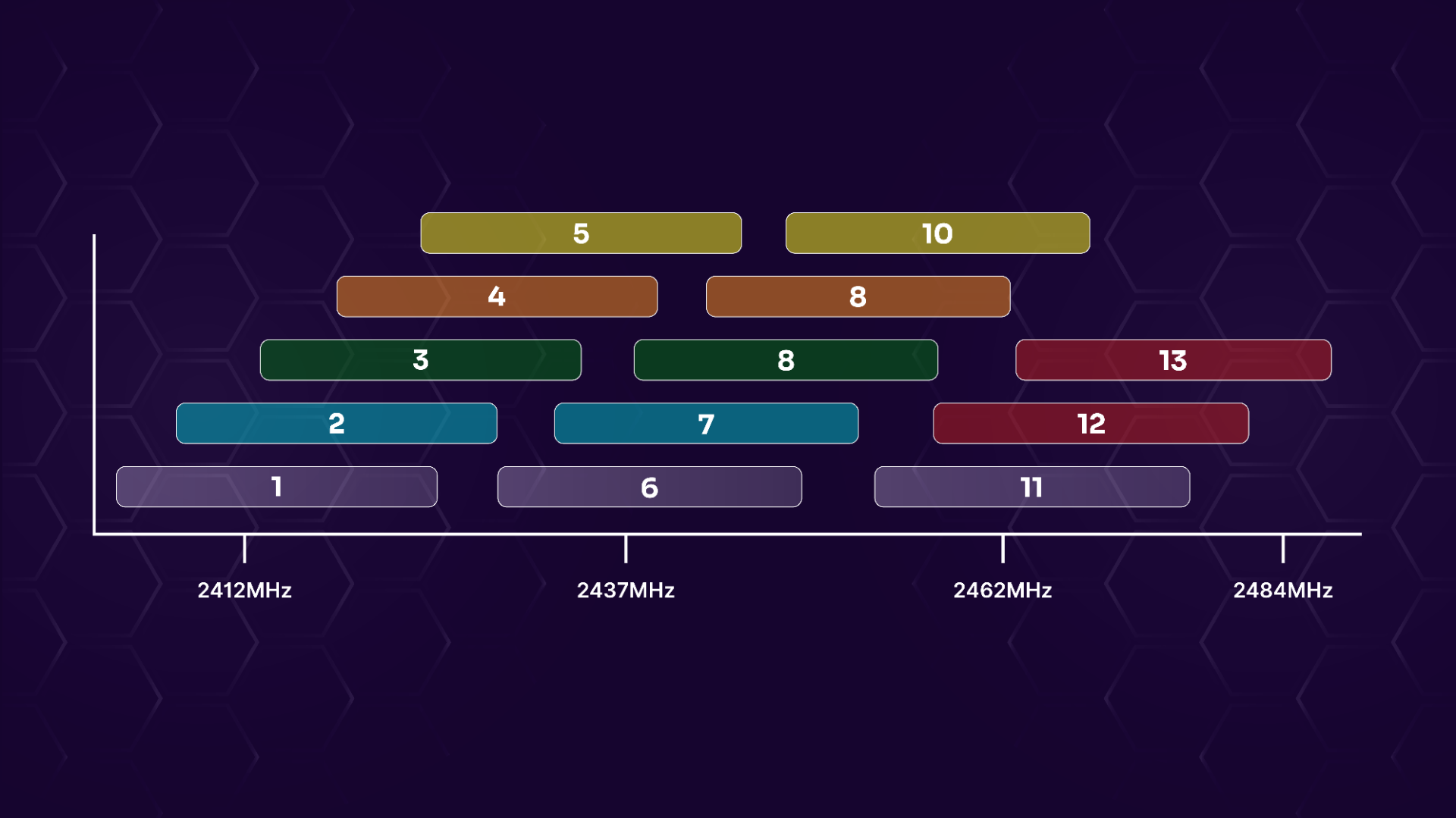
Figure 3: 802.11g/n channels
Note that channel 14 was only available in Japan for 802.11b.
802.11a/b/g sometimes uses multiple antennas but shouldn't be confused for Multiple-Input Multiple-Output (MIMO), which we will discuss later in this module. 802.11a/b/g is Single Input Single Output (SISO), which is the opposite of MIMO. In the case of 802.11a/b/g, the use of multiple antennas is called antenna diversity.
1.2.5. IEEE 802.11n
IEEE 802.11n was intended to improve transfer rates and provide more range on 2.4 GHz and 5 GHz networks. There were two releases, first allowing speeds up to 74 Mb/s, and subsequently speeds up to 300 Mb/s. The first release is based on the draft, while the IEEE 802.11 was still working on it. The speed increase in IEEE 802.11n is due in large part to its use of MIMO technology.
MIMO uses multiple antennas, each with its own transmitter and receiver. It improves signal reception by taking advantage of the multipath propagation phenomenon. Normally, signals bounce off of objects such as walls, doors, etc., degrading reception quality. In contrast, MIMO leverages this issue to enhance reception.
802.11n allows for the use of up to four spatial streams and the equivalent number of antennas to send and receive at a higher transfer rate. Commercially, up to three streams are available and the channel width can be 40 MHz instead of 20 MHz, thus doubling the data rate.
A deep dive into spatial streams, commonly abbreviated as streams in Wi-Fi, is out of scope for this course. However, the number of streams will become important when analyzing networks as we will see later on.
802.11n also introduced a new mode called Greenfield mode. Greenfield mode introduces a new preamble (a pause that comes before a wireless signal hits a networking device) for 802.11n only, whereby only devices operating in 802.11n will be allowed on the network.
Finally, in 802.11n a 20 MHz channel is divided into subcarriers, similar to 802.11a/g. The 64 subcarriers are divided slightly differently. Four of them are used for pilots like in 802.11a/g but 52 are used for data (instead of 48) and thus eight are used as null.
Antennas
The number of streams, and therefore the rates that can be reached, depend on the number of antennas on the transmitter and receiver.
The notation format is txr:s
- t: Number of transmit (TX) chains
- r: Number of receiving (RX) chains
- s: Maximum number of spatial streams the radio can use
For example, a common configuration would be 2x2:2, where the radio has 2 TX chains, 2 RX chains, and 2 streams. A 3x3:3 has 3 RX, 3 TX, and 3 streams.
This notation is not only used for 802.11n but also for any other amendment using MIMO.
You may encounter a slightly different notation format: tTrR. The two configurations above would be 2T2R, and 3T3R. The number of streams is not present in this format. Generally, we can assume that the number of streams is equal to the highest of the two numbers present.
The number of antennas doesn't always equate to the number of streams/chains, but the number of antennas is always greater or equal to the number of streams/chains. As such, a device with four antennas could very well have three streams or even two.
For example, the Alfa AWUS1900 wireless adapter has four antennas (four transmit and receive chains) but is a three spatial stream device: 4x4:3.
Warning
When analyzing networks, the number of streams will be crucial information, as we need a device with as many streams (or more) in comparison to what the client has. With too few streams, we won't be able to decode the communication.
MCS Rates
802.11n uses different modulations, coding rates, and streams to achieve speeds of up to 600 Mbit (450 Mbit commercially). A Modulation and Coding Scheme (MCS) rate is just a number that refers to a specific modulation and coding rate, and, in the case of 802.11n, the number of spatial streams in use. The rate also depends on the bandwidth of the channel, and to a lesser extent, the guard interval which is the interval between frames.
The coding rate (in the fourth column of the chart below) of a forward error correction code is the non-redundant portion of useful data. It is usually expressed in k/n, where for k bits of information, there is a total of n bits. n-k bits are redundant for error correction.
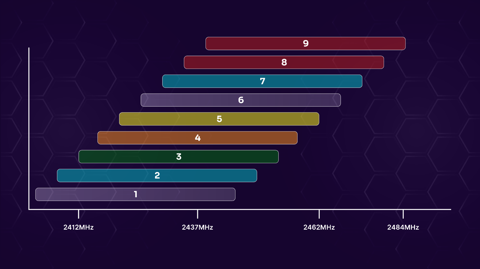
Figure 4: HT40+ channels in 2.4GHz
HT40- starts at channel 5 and the last HT40- is 11 (13 for Europe).
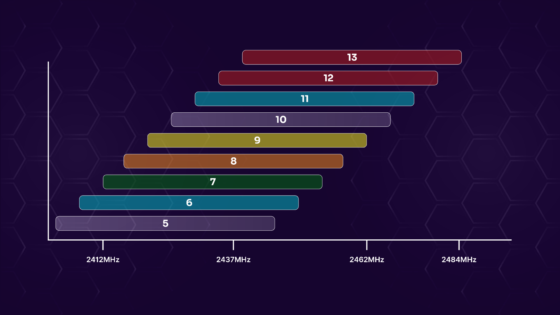
Figure 5: HT40- channels in 2.4GHz
1.2.6. IEEE 802.11ac
Due to the requirement of 80 MHz channels, 802.11ac is 5 GHz only.
Optionally, 802.11ac can have up to eight spatial streams and do transmit beamforming (technically, this should probably be called beam steering). Beamforming combines elements in an antenna array to steer the RF transmission in the direction of a specific device or group of devices.
802.11ac supports MCS 8 and 9 using 256-QAM but the receiver must be in close physical proximity to the transmitter. Some devices are also capable of 1024-QAM to increase rates even more. In this case, the transmitter has to be even closer (likely in the same room) since the signal required to reach those rates needs to be very strong. QAM-1024 isn't part of 802.11ac, and for that reason, hardware support is limited to certain vendors.
The interval between transmitted frames, known as the Guard Interval (GI), is 800 ns by default. It can be shortened (400 ns), which increases data rates slightly.
We won't go into Quadrature Amplitude Modulation (QAM) in this course, but here are a few basics. The number in QAM (and some other modulations) indicates how many possibilities it can represent at a time. The higher the number, the more data can be transmitted at a time. On the other end, the receiver must be able to decode the transmission. Precisely identifying the data sent without errors gets increasingly harder, thus requiring more complex hardware and a higher quality signal.
This is similar to recognizing tones of different frequencies. Discerning 16 or 32 distinct tones across the spectrum of frequencies we can hear is fairly easy, even with cheap headphones. However, in order to distinguish tones in between the ones we previously recognized, we might need headphones with better hardware to render the sounds precisely, so we can recognize them accurately. The room also needs to be increasingly quiet as well. It's the same for Wi-Fi.
802.11ac has been split in two waves, each of which brings different features. The first wave is based on a draft version of 802.11ac (2.0). The second wave is based on the final version.
We need to briefly return to 802.11n for a moment in order to discuss a key difference between Wave 1 and Wave 2. You may recall that 802.11n was MIMO. More accurately, we could have said it was Single User MIMO (SU-MIMO), though this is implied with 802.11n. 802.11ac Wave 1 is also SU-MIMO, but Wave 2 is Multiuser MIMO (MU-MIMO).
SU-MIMO devices transmit to one device at a time. In an environment where an AP had three transmit streams and three devices using one stream each, the AP could not combine transmission to all devices at the same time, but only to a single device.
Wave 2 is slightly different. Using the example above, it could handle all three devices at the same time. There are other requirements such as location and compatibility with MU-MIMO. It is one-way, limited to the downlink, going toward the stations.
Wave 2 also brought 160 MHz channels or two non-contiguous 80 MHz channels. The two channels can be in separate parts of the 5GHz spectrum.
Finally, 802.11ac has the same setup for subcarriers as 802.11n: 52 are data, 4 are pilots, and the 8 are null.
Rates
802.11ac rates are simplified (unlike 802.11n, where the numbers kept increasing with the number of streams). All modulations are available with any number of streams and thus the MCS value goes between 0 and 9 (10 with some proprietary rates using 1024-QAM).
The same website, MCSIndex.com can be used to look up 802.11ac rates.
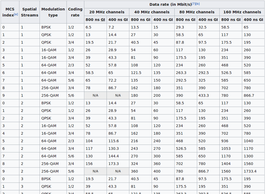
Figure 6: Excerpt of 802.11ac MCS rates (source: Wikipedia)
1.2.7. IEEE 802.11ad
802.11ad is also called WiGig.
It allows communications at high speed (multi-Gigabit) of audio, video, and data and delivers speeds between 385 Mbps to 6.7 Gbit/s using:
We won't go into a detailed explanation of these modulations here.
802.11ad allows operations in the 60 GHz band with 2.16 GHz of bandwidth. Transmissions at this frequency are absorbed by atmospheric oxygen, which limits its range.
Each 802.11ad channel has a bandwidth of 2.16GHz.
| Channel | Center frequency |
|---|---|
| 1 | 58.32GHz |
| 2 | 60.48GHz |
| 3 | 62.64GHz |
| 4 | 64.8GHz |
| 5 | 66.96GHz |
| 6 | 69.12GHz |
Table 2 - 802.11ad channel list
Frequency Bands
The available frequencies for 802.11ad depend on the region, meaning that some channels may not be available everywhere:
- USA: 57.05 GHz - 71GHz
- Canada: 57.05 GHz - 64GHz
- South Korea: 57 - 64 GHz
- Europe, Japan, and Australia: 57 - 66 GHz
- China: 59 - 64 GHz and 45 - 50 GHz (latter is also known as China Milli-Meter Wave, CMMW)
1.2.8. IEEE 802.11ax
Also known as High Efficiency (HE), 802.11ax builds upon 802.11ac and also works on 2.4 GHz. 802.11ax aims to improve the station throughput in dense environments, such as venues with a large number of devices, while still being backwards compatible with legacy 802.11 devices. 802.11ax introduces 1024QAM and Orthogonal Frequency-Division Multiple Access (MU-OFDMA).
While 1024QAM allows devices to reach higher rates (up to ~1.2 Gbps per stream), the signal quality must be high in order to achieve them.
OFDMA is more efficient because it can allocate specific parts of a 20/40/80/160 MHz (or 80+80 MHz) channel to different users, thus allowing different users to transmit and receive at the same time without interference.
As mentioned earlier, OFDM can only transmit to one device at a time. OFDMA, on the other hand, can assign part of the subcarriers (and 4x smaller subcarriers, 78.125 kHz each), aka Resource Units (RU), to be more efficient and allow for other devices to transmit at the same time.
For a 20 MHz channel, there are now 256 subcarriers, or tones. Resource units allocated to different users can be as small as 26 tones (a), which make the smallest channel 2 MHz wide. Each of these resource units can have different rates, power levels, and thus bandwidth.
802.11ax has the same potential as 802.11ac in terms of spatial streams, 8x8:8. Unlike 802.11ac, this also applies to client devices, not only access points. Another difference is MU-MIMO on 802.11ac (or 802.11n) is downlink only, whereas in 802.11ax, it can be uplink as well if the client supports it.
1.2.9. IEEE 802.11h
Part of the 5 GHz spectrum is also used by radars (military, civilian, and weather radars, either fixed or mobile), unmanned aircraft systems, DoD communications, instrumentation used to track rockets, missiles, and control satellites, etc. Anything else on that frequency must be careful not to interfere with it. 802.11h provides Dynamic Frequency Selection (DFS) and Transmit Power Control (TPC) that are mandatory in Europe in countries regulated by ETSI for frequencies between 5.250 to 5.725 GHz.
Wi-Fi can interfere with radar for kilometers, even at low power. Here is what it looks like on a weather radar:
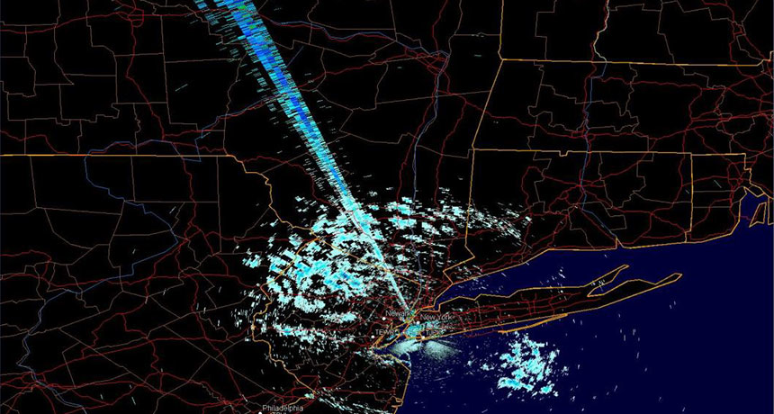
Figure 7: Wi-Fi interference on weather radar (source: sciencenews.org)
As soon as a radar is detected, DFS has to change the frequency for at least 30 minutes so it doesn't interfere with it. In the United States, DFS is mandated for frequencies between 5.250 to 5.350GHz and 5470 to 5.725GHz. Other countries may mandate other standards.
Let's consider one example implementation. On an enterprise access point, when certain 5GHz channels are selected, the AP scans for 60 seconds. Once it has finished the scan, it will either allow or not allow usage on that channel, depending on whether or not it found a radar. Detection is complex, and not always 100% reliable in identifying signals coming from other devices who have priority.
TPC allows for decreasing the amount of power to the minimum needed to maximize coverage, minimize co-channel interference, and interference with satellites and radars.
1.2.10. 802.11 Standard and Amendments Overview
The following table summarizes the main characteristics of the common 802.11 task groups:
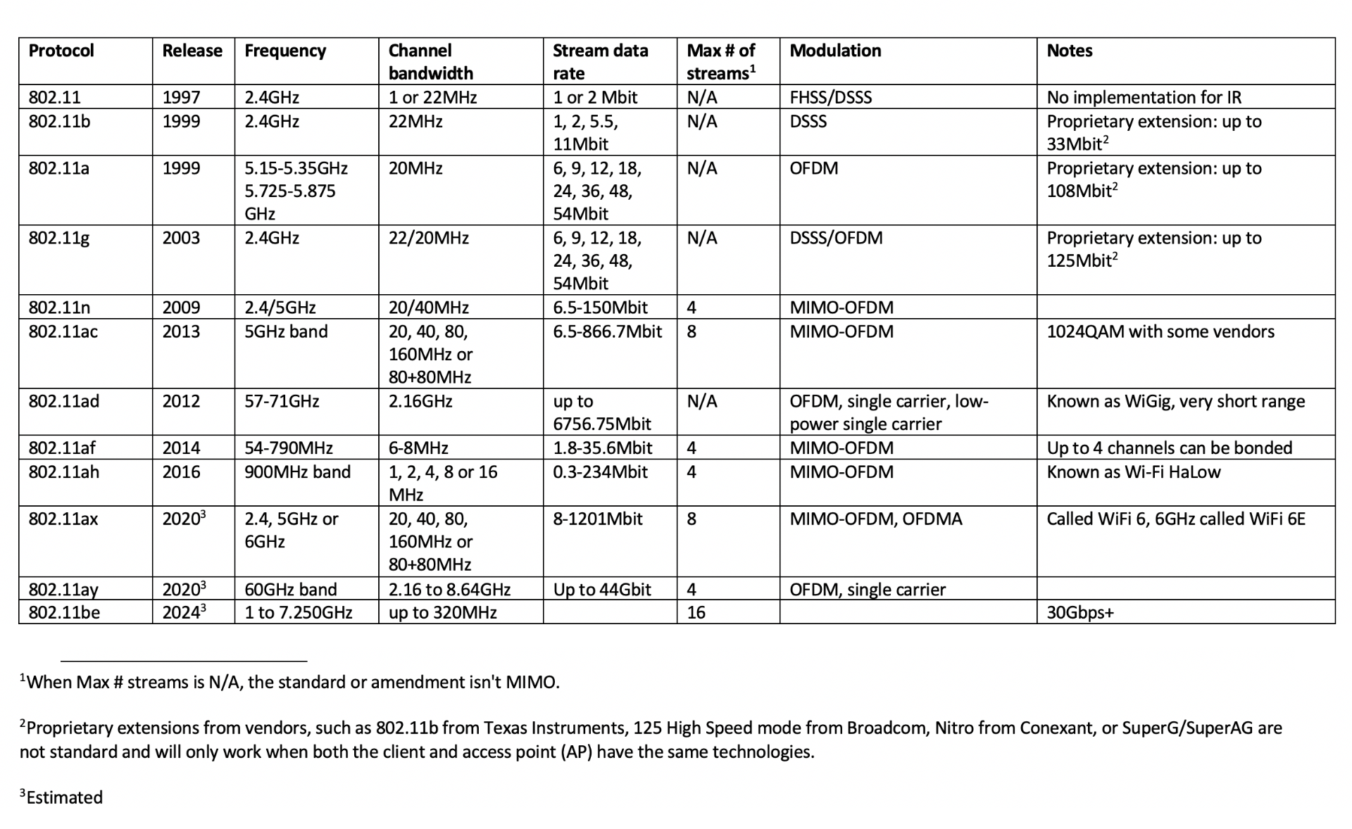
Figure 7: 802.11 task groups
1.3. Antenna Diversity vs MIMO
Although MIMO and antenna diversity both use multiple antennas, it is important not to get them confused with each other.
Antenna diversity is an older technology, and in the case of Wi-Fi, it meant using two antennas to improve a signal. Antenna diversity was sometimes used with 802.11a/b/g.
MIMO is a more recent wireless technology, which uses two or more antennas to transmit and receive. It has been used in 802.11n and onward, with a few exceptions.
Let's explore these two technologies in a bit more detail.
1.3.1. Antenna Diversity
Antenna diversity uses multiple antennas to improve the quality of a wireless link. It is often seen on long-haul trucks, where they have a Citizens Band (CB) antenna on both the driver and passenger side mirrors. The ideal distance between the antennas depends on the wavelength (which is calculated, in meters, by dividing 300 by the frequency in MHz). In the case of trucks and CB, the distance between the driver and passenger side mirrors is not ideal, but it still improves the signal.
Multipath propagation is an issue in wireless, where the signal bounces off objects and changes the path. Fading occurs and the signal can be different at two nearby locations. So, in the case of diversity, the receiver will use the antenna with the strongest signal.
Antenna diversity is fairly simple in comparison, and just needs to determine which antenna has the strongest signal, which could be done by checking the Modulation Error Ratio for the specific signal. In turn, when transmitting, using a single-pole, double-throw (SPDT) switch to select the antenna.
Antenna diversity is generally utilized to make improvements when receiving, but it can be used for transmitting as well.
1.3.2. MIMO
While antenna diversity selects the best (single) antenna to receive or transmit, MIMO splits the data into multiple streams and uses multiple antennas to send them. The receiver then combines the streams.
Some people get MIMO confused with Space-Time Block Code (STBC). STBC is similar to MIMO, but instead of splitting the signal in multiple parts, STBC duplicates it across multiple antennas. As a result, there is a higher chance the signal can be received in a noisy environment, where the receiver will select the best copy. Choosing either STBC or MIMO will depend on an algorithm in the transmitter.
1.4. Wrapping Up
In this module, we explained the standard and the common 802.11 amendments, from pure 802.11 to 802.11ax. We also went over 802.11h as it affects transmission in the 5GHz band, and a comparison between antenna diversity and MIMO.